
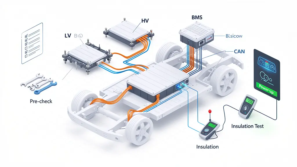
상업용 전기차에서 단일 배선 오류가 치명적인 열폭주 사건을 일으킬 수 있다는 사실을 알고 계셨나요? 중장비 배터리 팩 시스템 통합은 절대적인 정밀도를 요구합니다. 전기차 열 및 전기 통합 엔지니어로서, 제가 직접 공장에서 테스트한 설치 설계도를 안내해 드리겠습니다.
중장비 배터리 팩 시스템을 설치하려면 사전 조립 도구 점검, 기계적으로 팩을 고정하고, HV/LV 인터페이스를 연결하세요. 차폐된 하니스 배선, CAN 통신 테스트, 사전 EOL 절연 체크를 수행하세요. 마지막으로 안전한 전원 켜기 순서를 수행하고 BMS 기능을 검증하세요.
안전 위험을 유발하지 않고 설치 과정을 숙달할 준비가 되셨나요? 바로 10단계의 정확한 절차로 뛰어들어 봅시다.
1 준비 단계 (사전 조립)
렌치를 만지기 전에 작업 공간을 준비해야 합니다.
중장비 전기차 배터리 팩은 방대한 양의 밀집된 에너지를 저장합니다. 이들과 작업하려면 안전 및 품질 프로토콜을 엄격히 준수해야 합니다.
먼저, 엄격한 잠금/태그아웃 (LOTO) 절차를 실행하세요. 전체 시스템이 완전히 비전력 상태임을 확인해야 합니다. 규정 준수에 대한 복습이 필요하다면, 산업안전보건청(OSHA)의 LOTO 지침이 좋은 출발점이 될 수 있습니다.
다음으로, 장비를 갖추세요. 개인 보호 장비(PPE)는 양보할 수 없습니다. 얼굴 보호구, 절연 안전화, 고전압용 절연 장갑이 필요합니다.

마지막으로, 입고 품질 검사(IQC)를 수행하세요. 배터리 팩 하우징을 자세히 살펴보세요. 변형이 없어야 합니다. 고전압 커넥터의 산화 여부를 확인하고, 하니스 차폐가 손상되지 않았는지 검증하며, 올바른 REQ7 시리즈 부품 번호를 가지고 있는지 확인하세요.
교정된 도구를 준비하세요: 절연 공구 세트(≥1000V 등급), CAT III/IV 멀티미터, ESD 손목 스트랩, 절연 저항 메가옴미터.
2 배터리 팩 설치 (기계적 조립)
이제 무거운 금속을 이동할 시간입니다.
지정된 리프팅 포인트에 부착된 전용 리프팅 고정을 사용해야 합니다. 배터리 팩을 차량의 장착 프레임에 천천히 내리세요. 정밀도가 핵심입니다. 설치 구멍을 완벽하게 정렬하면서 기존 브래킷, 냉각 파이프 또는 하니스와의 간섭이 없도록 하세요.
정렬이 완료되면, 교정된 토크 렌치를 잡으세요.
M8 볼트의 경우, 22 ± 2 N·m의 토크를 적용해야 합니다. M10 볼트의 경우, 45 ± 5 N·m를 목표로 하세요.
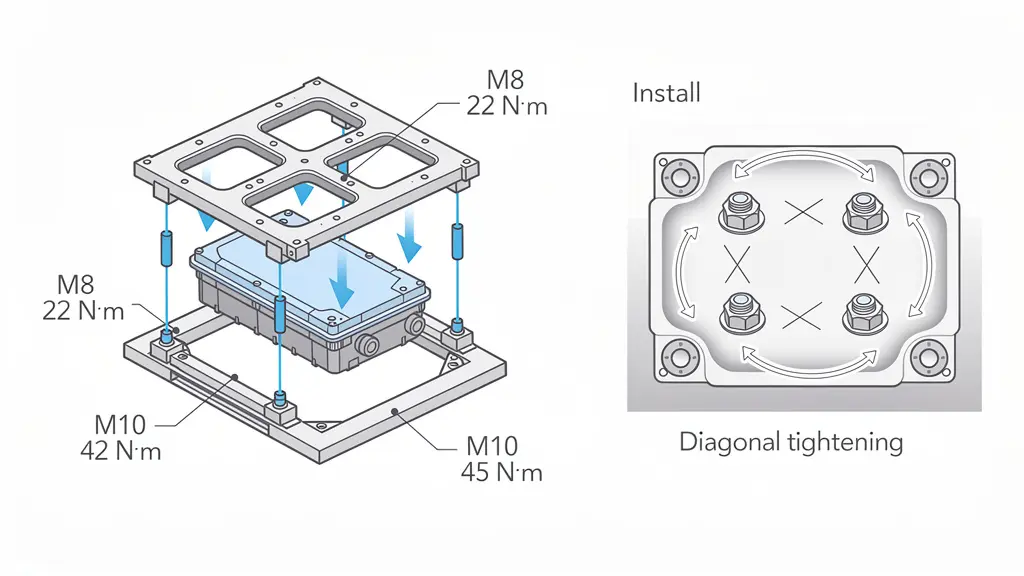
항상 대각선 순서로 볼트를 조이세요. 왜냐하면? 이는 배터리 박스 인클로저 전체에 균일한 하중 분포를 보장하며, 구조적 무결성과 누수 방지에 중요하기 때문입니다.
볼트 체결 강도에 관한 SAE 국제 연구에 따르면, 고르지 않은 토크는 중장비 진동 하에서 치명적인 조인트 실패로 이어질 수 있습니다.
이중 검증 검사를 수행한 후, 토크 마킹 페인트를 칠하세요. 이는 QA 팀에게 명확한 추적 가능성을 제공합니다.
3 고전압 인터페이스 설치 (HV 연결)
이제 본격적인 작업입니다. 고전압(HV) 연결은 집중이 필요합니다.
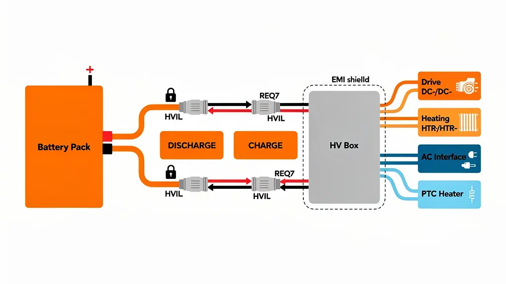
주요 HV 연결부터 시작하세요. 항상 이 정확한 순서를 따르세요:
배터리 팩 (+ / -)
방전 (+ / -)
충전 (+ / -)
HV 박스 입력 단자
황금률이 있습니다. 항상 음극 단자를 먼저 연결하고 양극 단자를 연결하십시오. 이 간단한 습관은 도구가 떨어졌을 때 우발적인 단락을 방지할 수 있습니다.
REQ7 커넥터를 함께 밀 때 “딸깍'하는 명확한 잠금 소리를 들으십시오. 절대 무리하게 삽입하지 마십시오. 딸깍 소리가 나지 않으면 고전압 인터록 루프(HVIL)가 작동하지 않습니다.
다음으로 HV 박스 통합으로 이동합니다. 드라이브 시스템 출력(DC+/DC-), 난방 시스템(HTR+/HTR-), AC 인터페이스 및 PTC 난방 회로를 연결하게 됩니다.
오결합을 방지하기 위해 안티 미스매치 키형 커넥터를 사용해야 합니다. 전자기 간섭(EMI)을 완화하기 위해 360° 차폐 접지를 달성하십시오.
4 저전압 및 통신 시스템 설치 (CAN/LV)
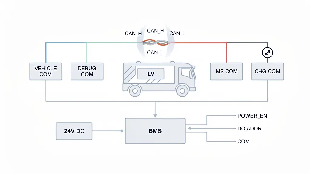
통신이 없는 중장비 EV는 비싼 벽돌에 불과합니다. 귀하의 저전압(LV) 및 컨트롤러 영역 네트워크(CANCAN.
) 설정은 중앙 신경계입니다.
인터페이스에는 다음이 포함될 가능성이 높습니다.
차량 통신
HMI COM
MS COMM
CHG COM
When running your CAN wiring, never reverse CAN_H (High) and CAN_L (Low).
You should use a shielded twisted pair cable. To ensure signal integrity, twist density should be at least 20 twists per meter. Make sure your shield is grounded at a single point only to prevent ground loops. You can read more about CAN bus physical layer standards via the ISO 11898 specification.
For your power supply signals, verify the 24V DC is grounded before you activate power. Check your POWER_EN (Power Enable) signal and ensure your DO_ADDR addressing is configured correctly for your Battery Management System (BMS).
5 충전 인터페이스 설치 (CHGCOM)
Charging heavy-duty EVs involves massive power transfer. Your CHGCOM installation must be flawless.
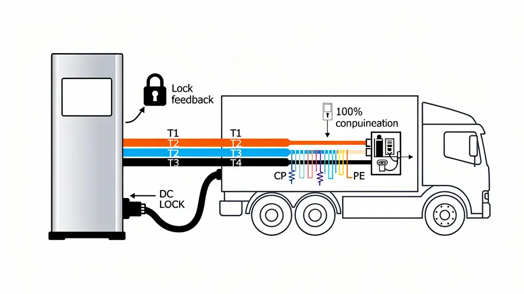
Identify your T1–T4 charging power channels and your communication signals (PP, CP, PE).
The electronic locking system (DC Lock) is a critical safety feature. Your installation must achieve 100% locking confirmation, complete with a lock feedback signal. If the cable can be pulled out during a high-power DC fast charge, it could cause a lethal electrical arc.
Ensure your Control Pilot (CP) and Proximity Pilot (PP) resistance meets regional specifications. For example, EU standards typically require a 1.5kΩ resistance. These protocols ensure the charger and vehicle handshake correctly before current flows, as outlined in the IEC 61851 standard for EV conductive charging.
Finally, strictly separate your charging communication lines from your HV power wiring to avoid signal corruption.
6 배선 하니스 설치
Routing wires might seem straightforward, but it’s where many start-ups fail.
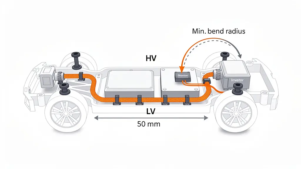
You must separate your HV and LV wiring by at least 50mm. Avoid long parallel runs between high-voltage power cables and sensitive signal lines.
HV cables must be shielded and mechanically protected. Heavy-duty EVs endure severe road vibrations. Because of this, you should secure all harnesses using anti-vibration clamps.
Use heavy-duty grommets anywhere a wire passes through a chassis hole. A chafed wire is a direct path to a short circuit. The IPC/WHMA-A-620 standard provides excellent benchmarks for acceptable wire harness routing and protection.
Always respect the minimum bend radius specified by your cable manufacturer. Bending a high-voltage cable too sharply can fracture the internal shielding and degrade the insulation.
7 시스템 안전 점검 (사전 EOL 체크)
Before your pack hits the End-of-Line (EOL), you have to prove it’s safe.
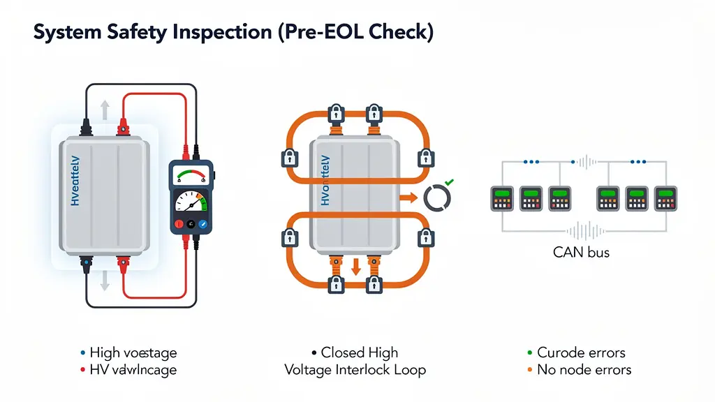
Grab your Megohmmeter. You need to run an insulation resistance test using a test voltage of at least 500V DC. You are looking for an insulation resistance of ≥500 MΩ. If it reads lower, you might have a pinched wire or moisture ingress.
Next, verify your High Voltage Interlock Loop (HVIL). The HVIL acts as a continuous low-voltage circuit that runs through all your HV connectors. You must confirm loop continuity. If there is an open loop condition, HV enable is strictly prohibited.
Finally, run a CAN communication check. Your network must be fully functional with zero frame loss and no node errors. The UN ECE R100 safety regulations mandate strict electrical safety standards that this test helps satisfy.
8 사전 전원 안전 점검
You are almost ready to flip the switch, but don’t rush. This checkpoint could save your vehicle architecture.
Run through this final checklist:
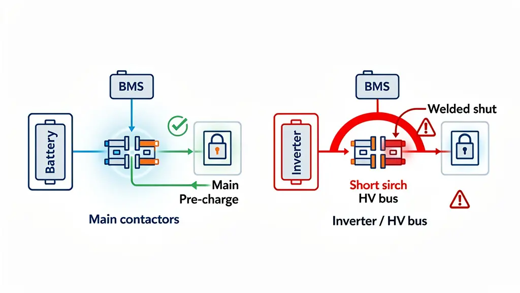
- Confirm there are no HV short circuits.
- Verify the pre-charge circuit is completely functional.
- Check the physical state of your main contactors (they should be open/normal).
- Ensure the BMS has successfully initialized.
- Scan for Diagnostic Trouble Codes (DTCs) and confirm there are no active faults.
- If you skip these checks and close the main contactor into a short circuit, the resulting inrush current can weld your contactors shut. This concept is heavily emphasized in ISO 26262 functional safety guidelines for road vehicles.
9 전원 켜기 순서
It is time to bring the system to life.
Powering up a high-voltage battery system is not like turning on a light bulb. You have to follow a strict sequential order to prevent component damage.
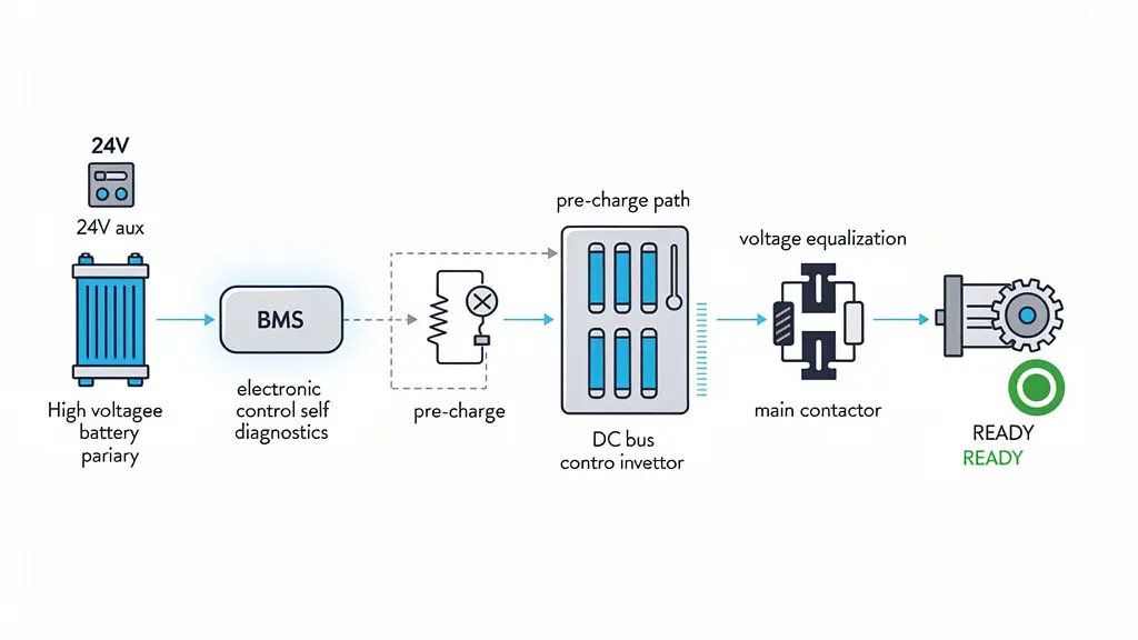
Here is the standard startup sequence:
- Turn ON the 24V auxiliary power.
- Allow the BMS to startup and complete self-diagnostics.
- Activate the pre-charge circuit. This slowly fills the capacitors in the inverter to prevent a massive spike in current.
- Wait for bus voltage equalization.
- Close the main contactor.
- The system officially enters the READY state.
- If you want to understand the deep electrical engineering behind this, IEEE offers extensive research on pre-charge resistor sizing and contactor lifecycle management.
10 기능 테스트
The system is powered up, but does it perform?
You need to run your system debugging and functional tests to ensure the pack operates as intended under load.
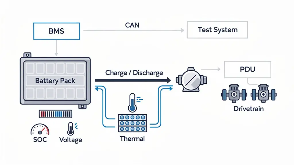
Test your CAN communication under active power to ensure EMI isn’t causing interference. Verify the State of Charge (SOC) accuracy by comparing the BMS reading to actual voltage calculations.
Perform a dynamic charge/discharge performance test. As current flows, monitor your thermal management system. Validate that your temperature sensors and liquid cooling plates are actively managing heat distribution.
Finally, run a high-voltage output verification to ensure the PDU (전력 분배 장치) is sending stable power to the drivetrains.
안전 적색선 (엄격히 금지)
Look, I cannot stress this enough. When working with High Voltage Battery Systems, there is absolutely zero margin for error.
Here are the safety red lines you must never cross:
❌ No live HV connector insertion or removal. Always de-energize first.
❌ No operation with an open HVIL loop. Do not bypass safety interlocks.
❌ No system energization without a passed insulation test.
❌ No operation with critical unresolved DTCs. If the BMS flags a fault, investigate it immediately.
❌ No bypassing of pre-charge failure conditions. If pre-charge fails, your contactors will fry.
결론
Mastering these 10 installation steps drastically reduces integration risks, ensuring your battery systems are built for demanding real-world operation. However, projects often fail when 기계적, 열, 전기 및 제어 시스템 are not developed as one coordinated solution. Ready to transform raw modules into a rugged, plug-and-play energy system? Contact 아스트레온 다이내믹스 today to make your heavy-duty battery integration practical, reliable, and fully deployment-ready.