
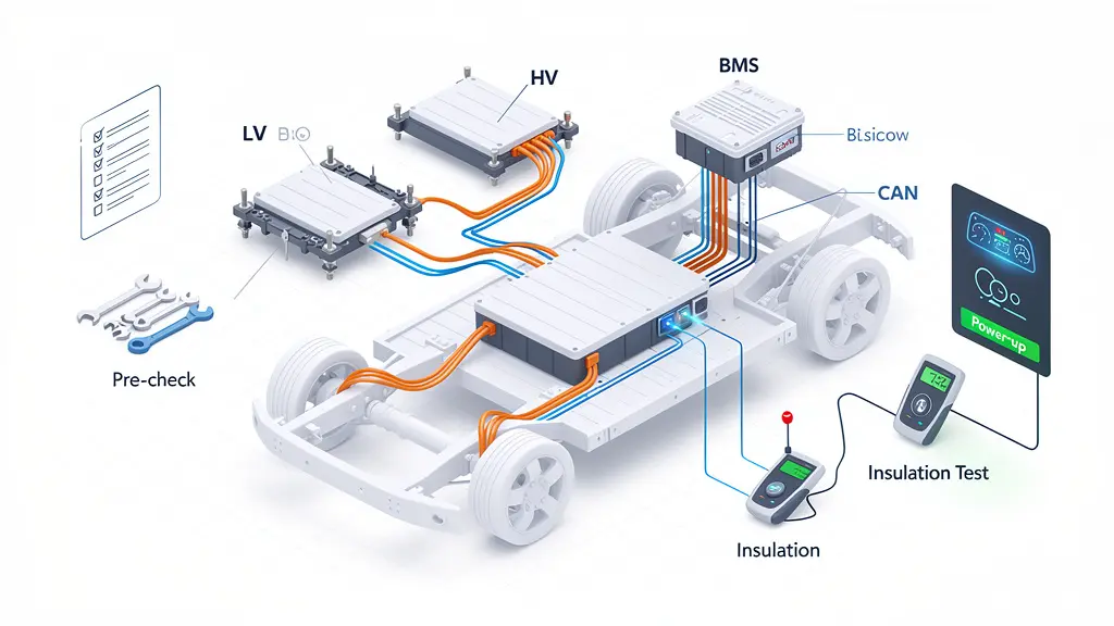
Did you know a single wiring error in a commercial EV can cause a devastating thermal runaway event? Integrating a Heavy-duty Battery Pack System requires absolute precision. As an EV thermal and electrical integration engineer, I’ll walk you through my exact factory-tested installation blueprint.
To install a heavy-duty battery pack system, perform pre-assembly tool checks, mechanically secure the pack, and connect HV/LV interfaces. Route shielded harnesses, test CAN communication, and conduct pre-EOL insulation checks. Finally, perform a safe power-up sequence and validate BMS functions.
Ready to master the installation process without triggering safety hazards? Let’s dive right into the exact 10 steps.
1 Preparation Stage (Pre-Assembly)
Before you even touch a wrench, you need to prepare your workspace.
Heavy-duty EV battery packs hold a massive amount of dense energy. Working with them requires strict adherence to safety and quality protocols.
First, execute a strict Lockout/Tagout (LOTO) procedure. You must confirm the entire system is fully de-energized. If you need a refresher on compliance, the Occupational Safety and Health Administration (OSHA) LOTO guidelines might be a great place to start.
Next, gear up. Personal Protective Equipment (PPE) is non-negotiable. You’ll need a face shield, insulated safety shoes, and insulated gloves rated for high voltage.

Finally, run an Incoming Quality Control (IQC) check. Look closely at the battery pack housing. There should be zero deformation. Check your high-voltage connectors for oxidation, verify the harness shielding is intact, and confirm you have the right REQ7 series part numbers.
Gather your calibrated tools: an insulated toolset (rated ≥1000V), a CAT III/IV multimeter, an ESD wrist strap, and an insulation resistance Megohmmeter.
2 Battery Pack Installation (Mechanical Assembly)
Now it’s time to move the heavy metal.
You should use a dedicated lifting fixture attached to the designated lifting points. Slowly lower the battery pack into the vehicle’s mounting frame. Precision is key here. You want to align the installation holes perfectly while ensuring no interference with existing brackets, cooling pipes, or harnesses.
Once aligned, grab your calibrated torque wrench.
For M8 bolts, you should apply 22 ± 2 N·m of torque. For M10 bolts, aim for 45 ± 5 N·m.
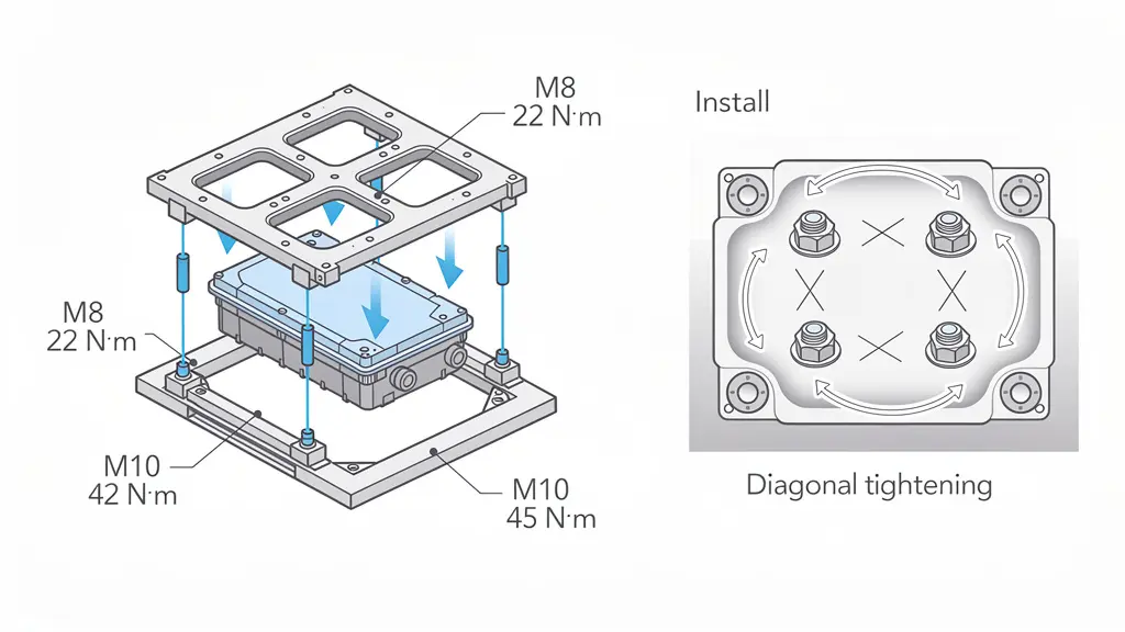
Always tighten the bolts in a diagonal sequence. Why? It ensures even load distribution across the battery box enclosure, which is critical for structural integrity and preventing water ingress.
According to research published by SAE International on bolted joint integrity, uneven torque can lead to catastrophic joint failure under heavy-duty vibration.
Perform a secondary double-verification inspection, then apply torque marking paint. This gives your QA team clear traceability.
3 High-Voltage Interface Installation (HV Connection)
This is where things get serious. High Voltage (HV) connections demand total focus.
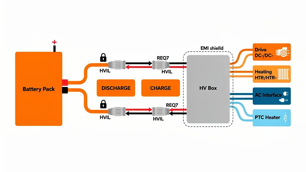
Start with your main HV connections. Always follow this exact sequence:
Battery Pack (+ / -)
DISCHARGE (+ / -)
CHARGE (+ / -)
HV Box input terminal
Here is a golden rule: always connect the negative terminal first, then the positive terminal. This simple habit may prevent accidental short circuits if a tool drops.
When pushing the REQ7 connectors together, listen for a clear locking “click.” Never force an insertion. If it doesn’t click, the High Voltage Interlock Loop (HVIL) won’t engage.
Next, move to your HV Box Integration. You’ll be connecting the drive system output (DC+/DC-), the heating system (HTR+/HTR-), the AC interface, and the PTC heating circuit.
You must use anti-mismatch keyed connectors to prevent plugging the wrong cables together. Ensure you achieve 360° shielding grounding to mitigate Electromagnetic Interference (EMI).
4 Low Voltage & Communication System Installation (CAN/LV)
A heavy-duty EV without communication is just an expensive brick. Your Low Voltage (LV) and Controller Area Network (CAN) setup is the central nervous system.
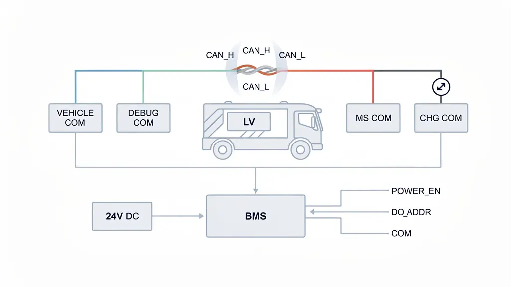
Your interfaces will likely include:
VEHICLE COM
DEBUG COM
HMI COM
MS COMM
CHG COM
When running your CAN wiring, never reverse CAN_H (High) and CAN_L (Low).
You should use a shielded twisted pair cable. To ensure signal integrity, twist density should be at least 20 twists per meter. Make sure your shield is grounded at a single point only to prevent ground loops. You can read more about CAN bus physical layer standards via the ISO 11898 specification.
For your power supply signals, verify the 24V DC is grounded before you activate power. Check your POWER_EN (Power Enable) signal and ensure your DO_ADDR addressing is configured correctly for your Battery Management System (BMS).
5 Charging Interface Installation (CHGCOM)
Charging heavy-duty EVs involves massive power transfer. Your CHGCOM installation must be flawless.
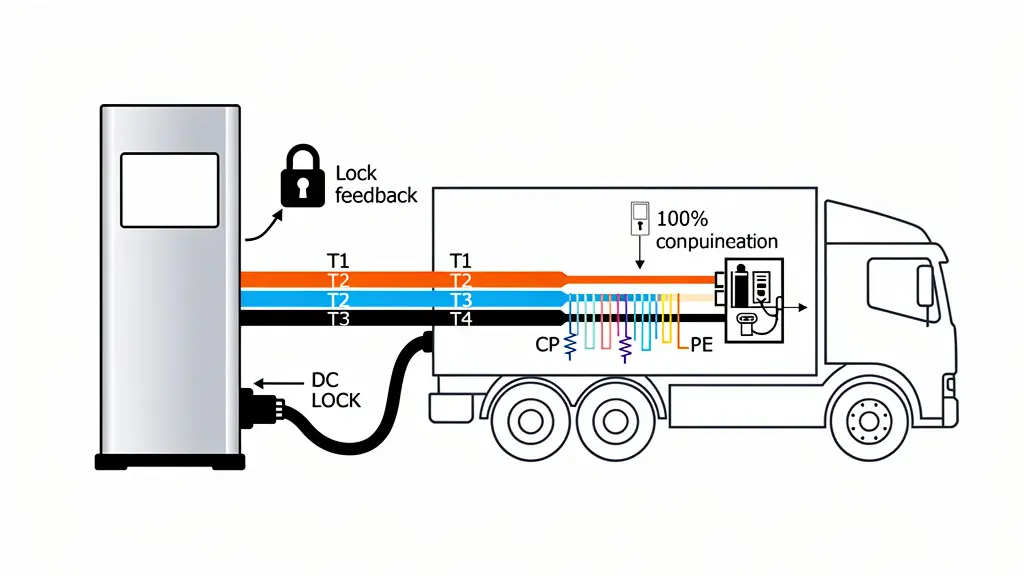
Identify your T1–T4 charging power channels and your communication signals (PP, CP, PE).
The electronic locking system (DC Lock) is a critical safety feature. Your installation must achieve 100% locking confirmation, complete with a lock feedback signal. If the cable can be pulled out during a high-power DC fast charge, it could cause a lethal electrical arc.
Ensure your Control Pilot (CP) and Proximity Pilot (PP) resistance meets regional specifications. For example, EU standards typically require a 1.5kΩ resistance. These protocols ensure the charger and vehicle handshake correctly before current flows, as outlined in the IEC 61851 standard for EV conductive charging.
Finally, strictly separate your charging communication lines from your HV power wiring to avoid signal corruption.
6 Wiring Harness Installation
Routing wires might seem straightforward, but it’s where many start-ups fail.
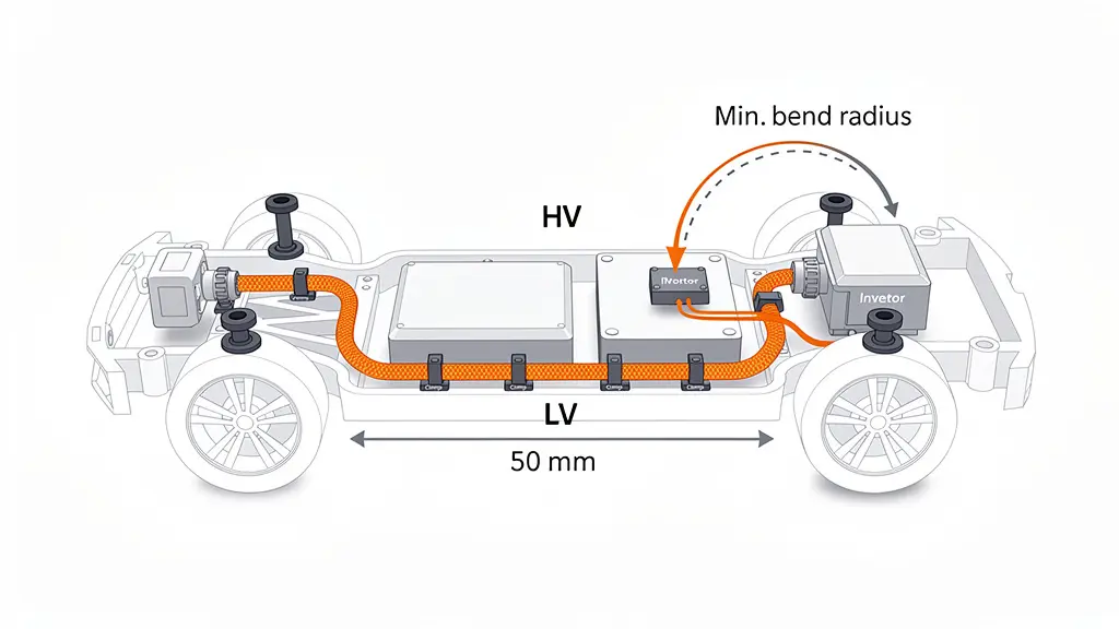
You must separate your HV and LV wiring by at least 50mm. Avoid long parallel runs between high-voltage power cables and sensitive signal lines.
HV cables must be shielded and mechanically protected. Heavy-duty EVs endure severe road vibrations. Because of this, you should secure all harnesses using anti-vibration clamps.
Use heavy-duty grommets anywhere a wire passes through a chassis hole. A chafed wire is a direct path to a short circuit. The IPC/WHMA-A-620 standard provides excellent benchmarks for acceptable wire harness routing and protection.
Always respect the minimum bend radius specified by your cable manufacturer. Bending a high-voltage cable too sharply can fracture the internal shielding and degrade the insulation.
7 System Safety Inspection (Pre-EOL Check)
Before your pack hits the End-of-Line (EOL), you have to prove it’s safe.
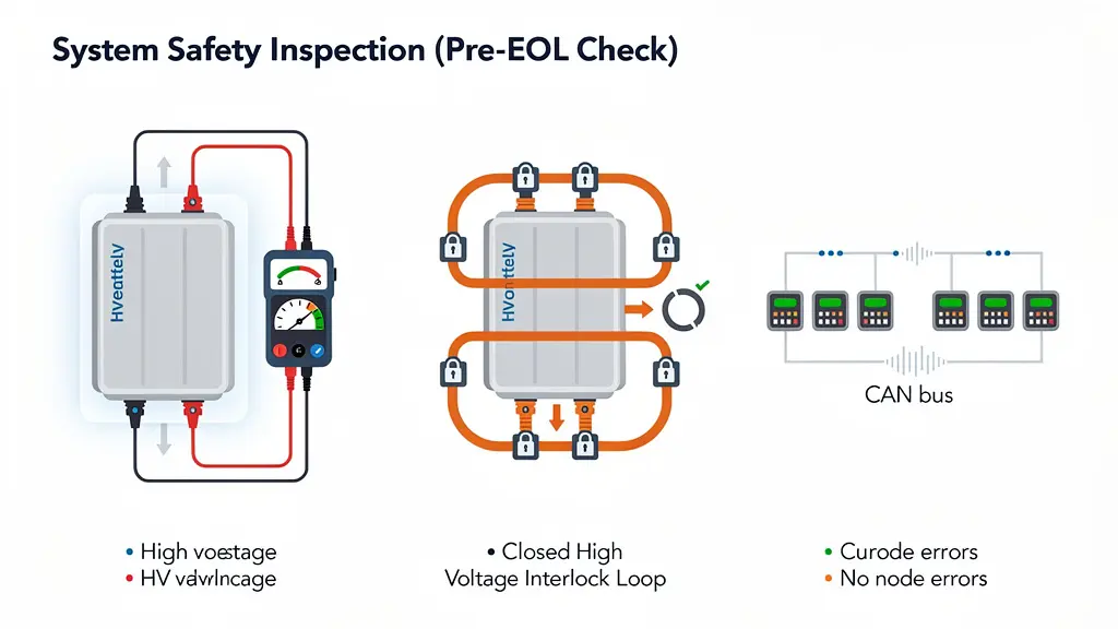
Grab your Megohmmeter. You need to run an insulation resistance test using a test voltage of at least 500V DC. You are looking for an insulation resistance of ≥500 MΩ. If it reads lower, you might have a pinched wire or moisture ingress.
Next, verify your High Voltage Interlock Loop (HVIL). The HVIL acts as a continuous low-voltage circuit that runs through all your HV connectors. You must confirm loop continuity. If there is an open loop condition, HV enable is strictly prohibited.
Finally, run a CAN communication check. Your network must be fully functional with zero frame loss and no node errors. The UN ECE R100 safety regulations mandate strict electrical safety standards that this test helps satisfy.
8 Pre-Power Safety Check
You are almost ready to flip the switch, but don’t rush. This checkpoint could save your vehicle architecture.
Run through this final checklist:
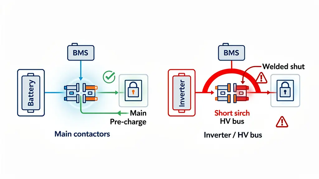
- Confirm there are no HV short circuits.
- Verify the pre-charge circuit is completely functional.
- Check the physical state of your main contactors (they should be open/normal).
- Ensure the BMS has successfully initialized.
- Scan for Diagnostic Trouble Codes (DTCs) and confirm there are no active faults.
- If you skip these checks and close the main contactor into a short circuit, the resulting inrush current can weld your contactors shut. This concept is heavily emphasized in ISO 26262 functional safety guidelines for road vehicles.
9 Power-Up Sequence
It is time to bring the system to life.
Powering up a high-voltage battery system is not like turning on a light bulb. You have to follow a strict sequential order to prevent component damage.
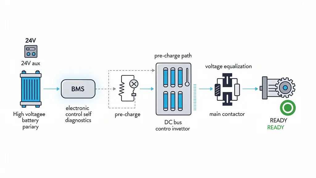
Here is the standard startup sequence:
- Turn ON the 24V auxiliary power.
- Allow the BMS to startup and complete self-diagnostics.
- Activate the pre-charge circuit. This slowly fills the capacitors in the inverter to prevent a massive spike in current.
- Wait for bus voltage equalization.
- Close the main contactor.
- The system officially enters the READY state.
- If you want to understand the deep electrical engineering behind this, IEEE offers extensive research on pre-charge resistor sizing and contactor lifecycle management.
10 Functional Testing
The system is powered up, but does it perform?
You need to run your system debugging and functional tests to ensure the pack operates as intended under load.
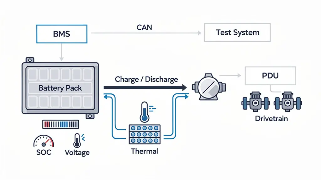
Test your CAN communication under active power to ensure EMI isn’t causing interference. Verify the State of Charge (SOC) accuracy by comparing the BMS reading to actual voltage calculations.
Perform a dynamic charge/discharge performance test. As current flows, monitor your thermal management system. Validate that your temperature sensors and liquid cooling plates are actively managing heat distribution.
Finally, run a high-voltage output verification to ensure the PDU (Power Distribution Unit) is sending stable power to the drivetrains.
Safety Red Lines (Strictly Prohibited)
Look, I cannot stress this enough. When working with High Voltage Battery Systems, there is absolutely zero margin for error.
Here are the safety red lines you must never cross:
❌ No live HV connector insertion or removal. Always de-energize first.
❌ No operation with an open HVIL loop. Do not bypass safety interlocks.
❌ No system energization without a passed insulation test.
❌ No operation with critical unresolved DTCs. If the BMS flags a fault, investigate it immediately.
❌ No bypassing of pre-charge failure conditions. If pre-charge fails, your contactors will fry.
Conclusion
Mastering these 10 installation steps drastically reduces integration risks, ensuring your battery systems are built for demanding real-world operation. However, projects often fail when mechanical, thermal, electrical, and control systems are not developed as one coordinated solution. Ready to transform raw modules into a rugged, plug-and-play energy system? Contact Astraion Dynamics today to make your heavy-duty battery integration practical, reliable, and fully deployment-ready.