
Wondering how CAN bus communication connects the complex components of an EV battery system? You are in the right place, because I am going to break down exactly how this critical network functions. I have spent years solving high-voltage integration challenges, and I will show you why mastering this communication protocol is non-negotiable for your vehicle.
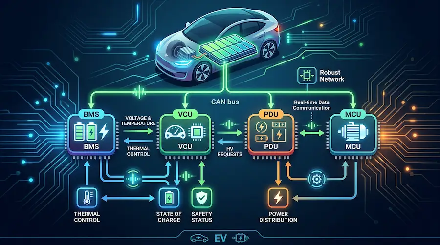
CAN (Controller Area Network) bus in an EV battery system is a robust vehicle network protocol. It allows microcontrollers like the BMS, PDU, and VCU to communicate and share real-time data without a host computer, ensuring battery safety, thermal management, and high-voltage control.
Let’s dive deep into the specific functions, components, and testing methods of CAN bus networks. I will show you exactly how this critical system keeps modern electric vehicles running safely, and how you can avoid common integration failures.
What Is CAN Bus In Simple Terms?
Think of the CAN bus as the central nervous system of an electric vehicle.
In the human body, your brain doesn’t need a separate, dedicated nerve wire connected to every single muscle fiber to send a signal. Instead, it sends signals through a shared nervous system, and the right muscles react.
The CAN bus does exactly the same thing for an EV battery system.
Instead of running heavy, expensive, point-to-point copper wiring between every single sensor and controller, all the electronic control units (ECUs) broadcast their messages onto a shared two-wire network.
Any device on the network can “hear” the messages, but they only act on the data that is relevant to them.

For example, when the Battery Management System (BMS) detects that the lithium-ion battery pack is getting too hot, it broadcasts a message on the CAN bus. The vehicle’s thermal management system hears this message and instantly spins up the liquid cooling pumps.
This happens in milliseconds. It is incredibly reliable, highly resistant to electrical noise, and fundamentally reduces the weight and complexity of the vehicle’s wiring harness.
CAN Bus Vs Automotive Ethernet
If you are a Systems Architect or an Electrical Engineer, you might be wondering if you should stick with CAN or move to Automotive Ethernet.
Here is the truth: both have their place, but they serve entirely different purposes.
CAN bus (and its faster sibling, CAN FD) is deterministic. This means messages are guaranteed to arrive within a highly predictable, strict timeframe. It is built for absolute reliability and fault tolerance in high-noise environments.
Automotive Ethernet, on the other hand, is built for massive bandwidth. It can handle up to 10 Gbps, making it perfect for Advanced Driver Assistance Systems (ADAS), LIDAR, and high-definition video streams.
Let’s look at a quick comparison:
Speed: CAN tops out at 1 Mbps (or up to 8 Mbps for CAN FD). Ethernet easily pushes 1 Gbps to 10 Gbps.
Latency: CAN is highly deterministic with microsecond latency for critical safety frames. Ethernet requires complex time-sensitive networking (TSN) switches to achieve similar determinism.
Wiring: CAN uses a simple unshielded or shielded twisted pair. Ethernet requires more complex, specialized cabling to prevent data loss.
Application in EVs: CAN is the undisputed king for the BMS, High-Voltage Power Distribution Unit (PDU), and Vehicle Control Unit (VCU). Ethernet handles the infotainment and autonomous driving brains.
For the core power and safety systems of your battery-powered platform, CAN bus remains the gold standard.

What Are The Purposes Of The CAN Bus Communication In An EV Battery System?
The primary purpose of CAN communication is to ensure the lithium-ion battery pack operates safely and efficiently.
Battery projects often fail at the integration stage, not because components are unavailable, but because mechanical, thermal, electrical, and control systems are not developed as one coordinated solution. The CAN bus is the glue that creates this coordination.
Here are the specific purposes it serves:
1. Real-Time Battery Monitoring
The BMS constantly calculates the State of Charge (SOC) and State of Health (SOH) of the battery. It broadcasts this data over the CAN bus so the dashboard can display your remaining range, and the motor controller knows exactly how much power it can safely draw.
2. Thermal Management Triggering
High-performance platforms, like electric trucks and marine vessels, have stringent requirements for liquid cooling. When cell temperatures rise during fast charging or heavy acceleration, the BMS sends a CAN request to the cooling system to adjust pump speeds and valve positions.
3. High-Voltage Safety And Contactor Control
The PDU/HV Control Box is responsible for physically connecting and disconnecting the high-voltage battery from the vehicle. If the BMS detects a critical fault—like a thermal runaway event or a severe over-voltage—it instantly sends a high-priority CAN message to the PDU to open the main contactors, cutting power to save the vehicle.
4. Charging Coordination
When you plug in an EV, the vehicle does not just blindly accept power. The BMS uses the CAN bus to talk to the DC fast charger, negotiating the exact voltage and current limits in real-time to prevent cell degradation.
How Does The CAN Bus Communication Work In An EV Battery System?
To understand how it works, you need to understand two key concepts: differential signaling and message arbitration.

First, CAN uses two wires: CAN_High and CAN_Low.
When a module wants to send a digital “1” (recessive bit), both wires sit at 2.5 volts. When it wants to send a digital “0” (dominant bit), CAN_High jumps to 3.5 volts and CAN_Low drops to 1.5 volts.
Because the system reads the difference in voltage between the two wires, it is highly immune to the massive electromagnetic interference (EMI) generated by high-voltage EV inverters. If an electromagnetic spike hits the cable, it hits both wires equally, and the voltage difference remains exactly the same.
Second, CAN uses a priority-based message system called Non-Destructive Bitwise Arbitration.
Every message has an identifier (ID). The lower the ID number, the higher the priority.
If the infotainment system tries to send a message at the exact same millisecond that the BMS tries to send a critical “Over-Voltage Fault” message, the system looks at the IDs. The BMS fault message will have a lower ID (higher priority). The infotainment system will instantly stop transmitting, allow the BMS message to go through, and then try again later.
This ensures that intelligent control messages always win the race.
What Does The CAN Bus Communication Consist Of In An EV Battery System?
If you are a Vehicle Integration Engineer or a Purchasing Manager sourcing parts, you need to know exactly what hardware makes up this network.
At a high level, the network consists of multiple nodes connected to a central bus. In an EV battery system, this consists of:
1. The Battery Management System (BMS) Node
This is the brain of the battery. It includes a CAN controller (which formats the data into frames) and a CAN transceiver (which turns the digital frames into physical voltage pulses on the wires). We often integrate intelligent BMS architectures designed specifically for demanding environments 3.
2. The PDU / HV Control Box Node
The Power Distribution Unit uses its CAN node to receive commands from the VCU or BMS to close pre-charge circuits and main relays.
3. The Vehicle Control Unit (VCU) Node
The VCU acts as the master commander. It takes inputs from the throttle pedal and sends CAN torque requests to the inverter, while simultaneously checking the BMS CAN data to ensure the battery can handle the load.
4. The Physical Layer
This includes the shielded twisted-pair cables, standard automotive connectors (like TE Connectivity or Amphenol), and the critical 120-ohm terminating resistors located at the two furthest ends of the bus to prevent signal reflection.

If you are building off-highway or specialty vehicles, figuring out how to make all these nodes talk to each other is incredibly difficult. Tier-1 cell manufacturers are built for massive standard volume and often leave you with a massive engineering headache regarding how to make their raw modules talk to your vehicle.
This is where a turnkey integration partner becomes invaluable, helping define the system architecture and integrating the VCU communication seamlessly.
What Are The Benefits Of The CAN Bus Communication?
CAN bus has survived for decades in the automotive industry for a reason. Here is why it remains the absolute best choice for EV battery systems:
Extreme Reliability: The differential signaling I mentioned earlier makes it practically bulletproof against the EMI generated by high-voltage EV motors.
Reduced Weight and Cost: By using a single twisted pair of wires for dozens of devices, OEMs save a massive amount of copper. In heavy-duty vehicle manufacturing, this weight reduction directly translates to better battery range.
Centralized Diagnostics: Because every message travels across the same bus, a technician can plug an OBD-II scanner into a single port and read the health of the BMS, the PDU, and the cooling system all at once.
Plug-and-Play Scalability: Need to add an extra datalogger or a secondary display? You don’t need to rewire the whole vehicle. You just tap into the existing CAN bus and program the new device to listen to the right IDs.
What Are The Disadvantages Of The CAN Bus Communication?
Despite its brilliance, CAN is not perfect. If you are a CTO or R&D Director mapping out your next-generation platform, you must be aware of these limitations:
Limited Bandwidth: Classic CAN tops out at 1 Mbps. While fine for relay commands and temperature readings, it chokes if you try to push large datasets, like battery impedance spectroscopy charts or camera feeds.
Security Vulnerabilities: CAN was designed for reliability, not cybersecurity. It lacks native encryption. If a malicious actor gains access to the bus, they can easily “spoof” messages—for instance, telling the PDU to open the high-voltage contactors while the vehicle is driving on the highway.
Network Load Issues: If you add too many devices (nodes) to a single bus, network utilization can exceed 70%. When this happens, lower-priority messages get constantly blocked by higher-priority ones, leading to dropped frames and system lag.
How To Test For CAN Bus Communication In An EV Battery System?
If you are a Testing Engineer or Program Manager overseeing final deployment, you cannot just cross your fingers and hope the communication works.
Rigorous testing is a mandatory step, especially for applications like electric mining vehicles or marine vessels that demand highly reliable, explosion-proof systems .
Here is how professionals test the CAN network:

1. Physical Layer Testing
Before looking at software, I always grab an oscilloscope. I probe the CAN_High and CAN_Low lines to ensure the idle voltage is sitting at exactly 2.5V. I look for clean, square voltage pulses without any rounded edges or electrical noise spikes. I also use a multimeter with the power off to ensure the bus resistance measures exactly 60 ohms (two 120-ohm resistors in parallel).
2. Protocol Layer Testing
Next, I hook up a CAN sniffer tool, like a Vector CANalyzer or a PCAN-USB interface. This allows me to read the raw hexadecimal traffic on a laptop. I check to see if the BMS is correctly transmitting its 11-bit or 29-bit CAN IDs at the correct cycle times (e.g., every 10 or 100 milliseconds).
3. Fault Injection Testing
You must know how the system reacts when things go wrong. I will intentionally short the CAN_High wire to the ground to see if the BMS successfully logs a communication loss fault and if the vehicle enters a safe “limp mode.”
Manufacturing should always be governed by 100% End-of-Line (EOL) testing protocols to catch these integration issues before they reach the field.
Conclusion
Understanding CAN bus communication is the key to unlocking safe, reliable, and intelligent control in any EV battery system. It bridges the gap between raw cell chemistry and your customized vehicle’s overarching control strategy.
However, integrating an intelligent BMS, a high-voltage PDU, and seamless VCU communication into a fully certified, plug-and-play energy system is an enormous engineering challenge.

If you are a Vehicle Integration Engineer struggling to make Tier-1 battery modules talk reliably to your heavy-duty, marine, or off-highway platform, you might need an engineering-driven integration partner.
At Astraion Dynamics, our business model is simple: You control the chemistry, we master the engineering. We support battery system programs from concept to commissioning, ensuring your CAN architecture is flawless and deployment-ready.
Reach out to our engineering team today to discuss your platform constraints, and let’s get your next EV project successfully integrated and out in the field.
