
Designing a high-performance battery pack without nailing the thermal management is a recipe for catastrophic failure. If you are struggling with thermal runaway risks, inefficient cooling, or premature pump failures in your electric platform, flow pressure drop is likely the hidden culprit you need to address immediately.
Flow pressure drop in a battery cooling system is the loss of fluid pressure as coolant travels from the inlet to the outlet of a cold plate. It occurs due to frictional resistance inside the cooling channels, restricting fluid flow and forcing the coolant pump to work harder to maintain optimal temperatures.
Want to know exactly how to calculate, control, and optimize this crucial metric for your heavy-duty EV or marine platform? Keep reading.
What is the pressure drop in liquid cooling?
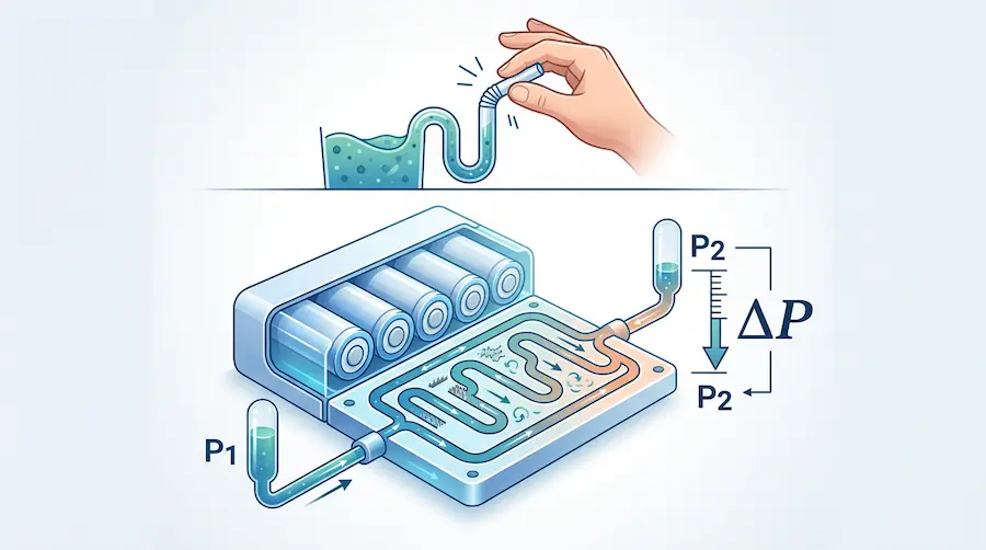
If you have ever tried drinking a thick milkshake through a very narrow straw, you intuitively understand pressure drop. In the context of liquid-cooled battery systems, pressure drop (often denoted as ΔP) is the difference in fluid pressure between the point where the coolant enters the battery cold plate and the point where it exits.
As the water-glycol mixture travels through the intricate micro-channels of a liquid cooling plate, it rubs against the walls of the aluminum enclosure. This friction, combined with the turbulence caused by bends, valves, and fluid splitters, causes a loss of mechanical energy. This energy loss manifests as a drop in pressure.
When you procure raw modules from Tier-1 cell manufacturers, they are built for massive standard volume, but they often leave you with a massive engineering headache when it comes to figuring out how to cool and package them safely 6. Getting the liquid cooling right—specifically managing this pressure drop—is exactly where specialized engineering makes or breaks the system.
What is the rule of thumb for pressure drop?
As an engineering-driven integration partner, we evaluate thermal systems across various demanding applications. While specific numbers vary based on the pump curve and pack size, a solid rule of thumb in automotive and heavy-duty battery liquid cooling is to keep the pressure drop across the battery cold plate between 20 kPa and 50 kPa (roughly 0.2 to 0.5 bar or 3 to 7 psi) at the nominal flow rate.
If your pressure drop is below 20 kPa, your cooling channels might be too large, which can lead to laminar flow. Laminar flow is terrible for heat transfer because the fluid glides too smoothly, preventing the cooler fluid in the center of the channel from mixing with the hot fluid near the channel walls.
If your pressure drop exceeds 50-70 kPa, your channels are likely too restrictive. This will require a heavy, high-voltage, power-hungry pump to push the coolant through, draining your battery capacity just to keep the system cool.
Does faster flow mean lower pressure?
No, it does not. This is a common point of confusion that trips up many junior engineers.
You might be thinking of Bernoulli’s principle, which states that in a streamlined fluid flow, an increase in velocity happens simultaneously with a decrease in static pressure. However, in the closed-loop piping of a battery cooling system, we are dealing with frictional pressure loss.
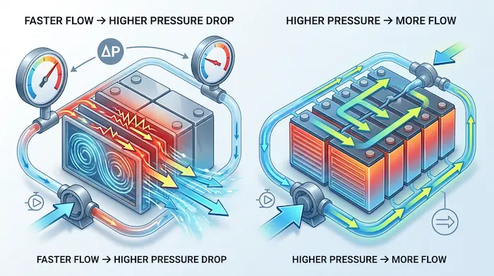
When you force fluid to flow faster through a fixed liquid cold plate, the friction between the fluid and the channel walls increases dramatically. Therefore, faster flow actually means a higher pressure drop. In fact, if you double the flow rate of your coolant, the pressure drop doesn’t just double—it quadruples.
Does higher pressure mean more flow?
Yes, but we need to be specific about our terminology.
High static pressure in a system (like inflating a tire to a high PSI) does not create flow. Fluid only moves when there is a pressure difference (differential pressure) between two points.
If your coolant pump generates a higher differential pressure across the inlet and outlet of the battery pack, it will force more fluid through the cooling channels, resulting in a higher flow rate. This is why heavy trucks and marine vessels, which have high demands for battery pack durability and liquid cooling, rely on powerful pumps to maintain high flow rates through extensive cooling networks.
How do you calculate pressure drop?
To get the exact pressure drop, thermal engineers rely on the Darcy-Weisbach equation. This is the gold standard for calculating frictional pressure loss in a pipe or cooling channel.
The formula looks like this:
ΔP = f * (L/D) * (ρ * v² / 2)
Let me break down what these variables mean for your battery pack:
ΔP (Pressure Drop): The metric we are solving for.
f (Friction Factor): A dimensionless number depending on whether your flow is smooth (laminar) or chaotic (turbulent), and how rough your cold plate channels are.
L (Length): The total length of the cooling channels.
D (Hydraulic Diameter): The effective diameter of your cooling channels.
ρ (Fluid Density): The density of your coolant (usually a 50/50 water-ethylene glycol mix).
v (Velocity): How fast the fluid is moving.
Because projects typically begin with a strict review of packaging constraints and thermal targets, running these calculations via 3D thermal simulation is a mandatory step before any metal is cut.
What is the relationship between flow and pressure drop?
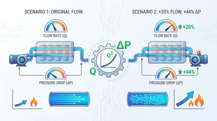
The relationship between flow rate (Q) and pressure drop (ΔP) is exponential, not linear.
Specifically, pressure drop is proportional to the square of the flow rate (ΔP ∝ Q²).
If it demands a 20% increase in cooling capacity and you decide to achieve this by simply increasing the flow rate by 20%, you will face a rude awakening. A 20% increase in flow (1.2x) will result in a 44% increase in pressure drop (1.2² = 1.44). Your pump might not be able to handle that sudden spike in resistance.
What is the formula for flow rate with pressure drop?
When sizing pumps and valves for a battery thermal management system, engineers often use the Flow Coefficient formula rather than doing raw Darcy-Weisbach math every time. The Flow Coefficient (Cv in Imperial, Kv in Metric) links flow rate directly to pressure drop.
The simplified formula for flow rate is:
Q = Cv * √(ΔP / SG)
Here is what that means:
Q: Flow rate (Gallons per minute or Liters per minute).
Cv: The flow coefficient (a constant based on your cold plate’s internal geometry).
ΔP: Pressure drop.
SG: Specific Gravity of your coolant (Water is 1.0; a 50/50 Water-Glycol mix is usually around 1.06).
This shows that to calculate the flow rate, you take the square root of the pressure drop. It reinforces why you need a massive amount of pressure to achieve just a small increase in flow.
How does pressure drop affect flow?
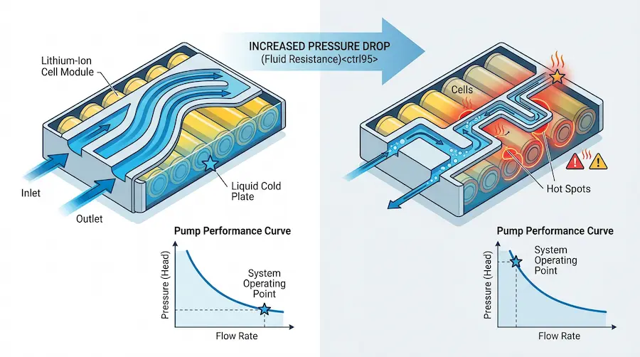
Pressure drop is essentially fluid resistance. It dictates where your system will operate on a “pump curve.”
Every liquid coolant pump comes with a performance curve provided by the manufacturer. The X-axis is Flow Rate, and the Y-axis is Pressure (Head). As pressure drop in your battery pack increases, the pump’s ability to push fluid decreases.
If your precision liquid cold plates are poorly designed with too many sharp 90-degree turns, the pressure drop will be immense. The pump will hit its maximum pressure limit before it can deliver the required liters-per-minute of flow. This leads to stagnant coolant, localized hot spots on your lithium-ion cells, and eventually, rapid cell degradation.
What happens if too much pressure is in the cooling system?
If your cooling system suffers from excessive pressure drop and your pump is straining to push fluid through, several catastrophic failures can occur:
Ruptured Cold Plates: High pressure can cause the aluminum plates to expand or burst.
Coolant Leaks: Seals, O-rings, and quick-connect fittings can fail under high pressure. If conductive water-glycol leaks onto high-voltage busbars, it will cause a catastrophic short circuit and potentially trigger a thermal runaway fire.
Pump Cavitation and Failure: Overworking the pump reduces its lifespan and can cause cavitation (micro-boiling), which eats away at the pump impeller.
This is precisely why battery projects often fail at the integration stage—not because components are unavailable, but because mechanical, thermal, and electrical systems are not developed as one coordinated solution. To prevent this, our in-house engineering team designs rugged IP67+ aluminum enclosures and relies on 100% End-of-Line testing protocols to ensure pressure integrity.
What effect causes rapid cooling when pressure drops?
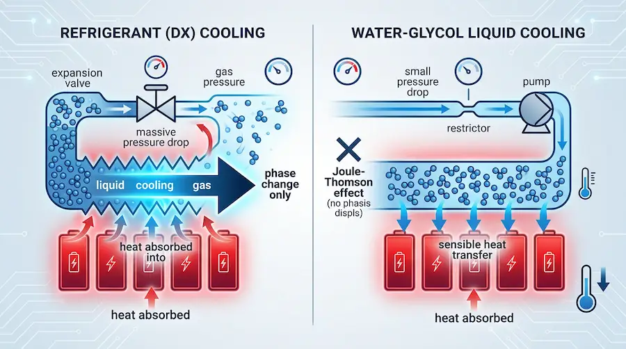
You might have heard that a sudden drop in pressure causes rapid cooling, and you are wondering how this applies to battery packs. This phenomenon is known as the Joule-Thomson effect.
However, a critical distinction must be made here. The Joule-Thomson effect primarily applies to gases and refrigerants undergoing a phase change (like in direct-expansion refrigerant cooling systems). When highly pressurized liquid refrigerant passes through an expansion valve, it experiences a massive pressure drop, boils into a gas, and absorbs a massive amount of heat, causing rapid cooling.
In a standard EV water-glycol liquid cooling loop, the fluid remains a liquid. It absorbs sensible heat rather than undergoing a phase change. Therefore, a pressure drop in a standard water-glycol system does not cause rapid Joule-Thomson cooling; it simply represents lost pumping energy.
How much pressure should be in a cooling system?
To keep a battery cooling system safe and efficient, you must manage two types of pressure: Operating Pressure and Test Pressure.
Operating Pressure: During normal operation, the static pressure in an EV battery cooling loop is usually kept relatively low, around 1 to 2 bar (14 to 30 psi). This is enough to prevent pump cavitation and keep the fluid stable, but low enough to protect the seals.
Test Pressure (Proof and Burst): Before any battery pack is commissioned, it must be pressure tested. Proof pressure testing is typically done at 2 to 3 times the operating pressure to ensure zero leaks.
Marine vessels, off-highway equipment, and heavy-duty electric trucks have highly stringent requirements for waterproofing and liquid cooling . Delivering fully integrated, plug-and-play power systems means these pressure benchmarks must be flawlessly validated before deployment.
You Control the Chemistry, We Master the Engineering
Are you a CTO, Chief Engineer, or Purchasing Manager dealing with the massive engineering headache of integrating raw battery modules into a specialized vehicle or vessel?
Tier-1 cell manufacturers will gladly sell you their raw modules at zero middleman markup, but they won’t help you design the precision liquid cold plates, intelligent BMS architectures, or high-voltage PDUs required to make them work.
That is exactly where Astraion Dynamics steps in. We are the ultimate “Bring Your Own Cells/Modules” integration hub for heavy-duty, marine, and off-highway applications. From initial 3D thermal simulation to flawless UN38.3 / ECE R100.3 homologation, we transform your procured raw modules into a rugged, fully certified, plug-and-play energy system.
Don’t let poor thermal management and pressure drop derail your electrification program.
We work with customers as an engineering-driven integration partner, supporting you from concept to commissioning. If you are ready to shorten development cycles and bring your battery-powered platforms into operation with greater confidence, we need to talk.
