

You’re designing the next generation of EVs, and things are getting complex fast. Between managing thermal runaway risks and optimizing high-voltage interlocks, you need a flawless roadmap to make the entire system work in harmony.
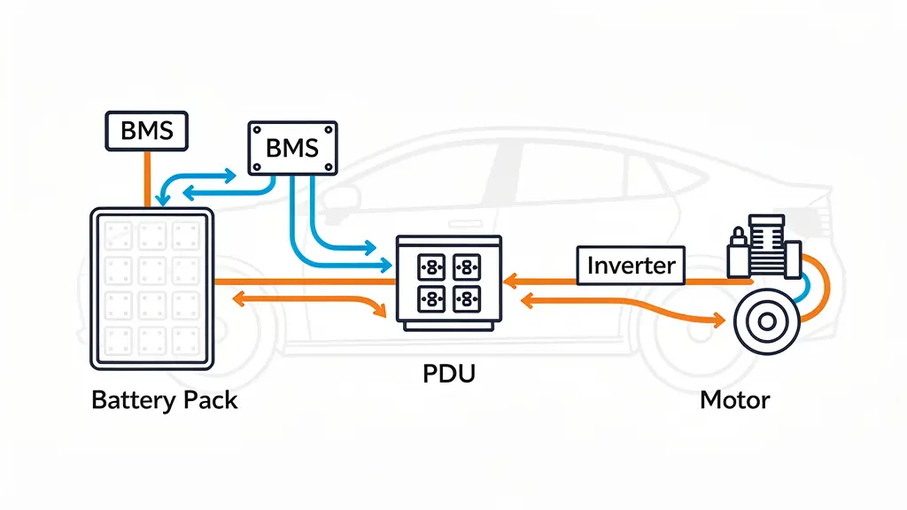
An EV electrical schematic diagram is a standardized 2D blueprint mapping the electrical connections, components, and logic circuits of an electric vehicle. It details how high-voltage power and low-voltage control signals flow between the battery, BMS, PDU, and drivetrain.
Want to know how this blueprint keeps both passenger cars and heavy-duty EVs running safely and efficiently? Let me break down the exact architectures and components you need to know to engineer a world-class electric vehicle.
What is the meaning of the electrical schematic diagram?
When I first started looking at EV architectures years ago, it felt like reading a foreign language. But once you understand the grammar, it all makes sense.
In simple terms, an electrical schematic diagram is the ultimate “source of truth” for your vehicle’s electrical engineering.
Unlike a mechanical CAD drawing that shows you what a lithium-ion battery pack physically looks like, a schematic diagram uses standardized symbols to represent how electrical components logically connect. It doesn’t care about the physical dimensions of your high-voltage cables. Instead, it cares about how the current flows from point A to point B.
Think of it as the nervous system map of your EV. It shows every wire, every connector, every fuse, and every communication bus (like CAN or LIN) that allows the vehicle’s brain to talk to its muscles.
What are the purposes of the electrical schematic diagram for EVs?
Why spend hundreds of hours perfecting these diagrams before a single physical prototype is built?
Because in the world of high-voltage EVs, guessing isn’t an option. The stakes are simply too high.

Here are the primary purposes of mapping out your electrical schematic:
- Safety and Compliance: Heavy-duty EVs operate at 600V, 800V, or even higher. Schematics prove to regulatory bodies that your High Voltage Interlock Loop (HVIL) and isolation monitoring meet strict ISO 26262 safety standards.
- System Integration: It ensures the Vehicle Control Unit (VCU) can actually communicate with the Battery Management System (BMS) and the motor inverter without electromagnetic compatibility (EMC) interference.
- Manufacturing Instructions: Your assembly line technicians rely on these diagrams to build wire harnesses and route cables correctly.
- Diagnostics and Troubleshooting: When a prototype fails a full-vehicle test, your system debugging engineers use the schematic to trace faults back to the exact pin on a specific connector.
Without a robust schematic, you don’t have an EV. You just have a very expensive metal box full of disconnected parts.
What is an example of an electrical schematic diagram?
Let’s look at a real-world scenario.
Picture the schematic for the high-voltage distribution network in a commercial electric truck.
At the far left of the page, you’ll see the symbol for the lithium-ion battery pack. From there, thick solid lines (representing high-voltage DC cables) route directly into the Power Distribution Unit (PDU/HV Control Box).
Inside the PDU boundary box on the diagram, you’ll see symbols for positive and negative main contactors, pre-charge relays, and pre-charge resistors.

From the PDU, the high-voltage lines branch out. One path goes to the traction inverter (which connects to the electric motor). Another path routes to the electric air conditioning compressor. A third path heads toward the DC fast charge station port.
Parallel to these high-voltage lines, you’ll see dashed lines indicating the low-voltage CAN bus network, tying the VCU, the Master BMS, and the PDU’s internal sensors together into one synchronized loop.
How does the electrical schematic diagram work for EVs?
It all comes down to logic and flow.
An electrical schematic diagram works by standardizing complex physics into universally understood symbols.
When you read it, you trace the flow of power and data. High-voltage lines are typically drawn thicker or color-coded (often orange in modern software) to distinguish them from the 12V/24V low-voltage control lines.
The diagram works by showing “states” and “conditions.” For example, the schematic dictates that high-voltage power cannot flow from the battery to the motor unless the VCU sends a specific low-voltage signal to close the contactors inside the PDU/HV Control Box.
It maps the exact sequence of operations. If a technician unplugs a high-voltage connector, the schematic shows how the HVIL circuit immediately breaks, signaling the VCU to open the contactors and isolate the battery, preventing a lethal shock.

What are the components of the electrical schematic diagram for EVs?
This is where the magic happens. A top-tier EV schematic is packed with specialized components.
Let’s break down the major players you will find on any modern EV schematic.
Lithium-Ion Battery Pack
This is the heart of the vehicle. On the diagram, it’s rarely just one symbol. It is usually depicted as a series of battery modules connected in series and parallel to achieve the target voltage and capacity.
BMS (Battery Management System)
The BMS is critical for battery safety and longevity. In high-capacity vehicles, the schematic will detail a Master-Slave BMS architecture:
Master BMS (BCU – Battery Control Unit): The brain. It calculates State of Charge (SOC) and State of Health (SOH), and communicates directly with the VCU.
Slave BMS (BMU – Battery Management Unit): The field workers. Placed directly on the battery modules, they monitor individual cell voltages and temperatures.
Cluster Architectures
In heavy-duty EVs with massive energy needs, you might see a Cluster setup. Here, multiple independent battery strings (each with its own BCU and BMU setup) are wired in parallel into a central control hub.
PDU / HV Control Box
The Power Distribution Unit is the traffic cop for your high voltage. The schematic will show the PDU housing the fuses, contactors, and current sensors. It’s the physical junction where power from the battery is split off to the motor, DC/DC converter, and thermal management heaters.
VCU (Vehicle Control Unit)
The central brain of the entire EV. The schematic positions the VCU as the master controller, taking inputs from the accelerator pedal, the brake system, and the BMS, and outputting torque commands to the inverter.
Charge Station Interface
The schematic must detail the charging ports (like CCS or CHAdeMO), showing both the high-voltage DC pins for fast charging and the low-voltage communication pins that let the EV “handshake” with the external Charge Station before power flows.

What are the benefits of the electrical schematic diagram for EVs?
You might be thinking, “This sounds like a massive amount of front-end engineering.”
You’re absolutely right. But the payoff is huge.
First, it drastically reduces development costs. By simulating the schematic in software, your R&D team can identify bottlenecks—like an undersized pre-charge resistor or a CAN bus layout prone to EMC interference—before purchasing expensive physical prototypes.
Second, it allows for seamless supply chain procurement. Your Purchasing Manager can look at the Bill of Materials (BOM) generated directly from the schematic and source the exact high-voltage connectors and communication cables required.
Finally, it ensures scalability. If you design a brilliant PDU/HV Control Box layout for a 12-meter electric bus, a clean schematic allows your engineering team to easily adapt that same architecture for an 18-meter articulated bus later.
How to design an electrical schematic diagram for EVs?
Designing an EV schematic isn’t something you do on the back of a napkin. It requires a rigid, systematic approach.
Here is the process I highly recommend:

Define System Requirements: Start with the basics. What is the peak motor power? What is the continuous discharge rate (C-rate) of the lithium-ion battery pack? Will it support 350kW fast charging?
Create a High-Level Block Diagram: Before drawing every single wire, create a block diagram showing the main sub-systems (Battery, PDU, Inverter, VCU) and how they interact.
Draft the High-Voltage Typologies: Map out the high-voltage paths first. Select your contactors, fuses, and cable gauges based on your peak current calculations.
Integrate Low-Voltage & Communication: Route your CAN/LIN networks. Ensure your Master BMS, Slave BMS, and VCU are properly networked with terminating resistors to prevent signal reflection.
Review and Simulate: Run the schematic through SPICE or MATLAB simulations. Check for voltage drops, transient spikes, and thermal limits.
How to choose the right electrical schematic diagram for EVs?
Choosing the “right” schematic isn’t about finding a one-size-fits-all template. It’s about matching the architecture to the vehicle’s specific mission profile.
If you are an engineer designing an urban delivery van, your primary constraint is cost and packaging space. You might opt for a highly integrated schematic where the PDU, On-Board Charger (OBC), and DC/DC converter are consolidated into a single physical unit (often called an “x-in-1” controller).
On the other hand, if you are a Chief Engineer building a Class 8 heavy-duty electric semi-truck, your primary constraint is thermal management and redundancy. You will want a highly decentralized, modular schematic. If one battery cluster fails, the schematic logic must allow the VCU to isolate that specific string while keeping the truck moving on the remaining power.
What is the best electrical schematic diagram for different EVs?
The best schematic always comes down to Architecture Typologies.
Let’s look at how the ideal schematics differ between vehicle classes.
Passenger EVs (Centralized Typology)
For everyday passenger cars, space is incredibly tight. The best schematic here features a highly centralized architecture.
You will see a single, large lithium-ion battery pack managed by a Master BMS, communicating with localized BMUs. The PDU/HV Control Box is usually integrated directly into the battery pack enclosure or the motor housing to save weight and reduce the length of expensive high-voltage cables.

Heavy-Duty EVs (Distributed/Modular Typology)
For electric buses, mining trucks, and construction equipment, a centralized design is often impossible. The batteries are simply too large and must be spread across the chassis.
The best schematic for a heavy-duty EV utilizes a distributed Cluster Architecture.
You will map out multiple independent battery packs.
Each pack has its own Slave BMS (BMU) and intermediate BCU.
These intermediate units report to a grand Master BMS.
The high-voltage power from each pack is routed into a massive, stand-alone PDU/HV Control Box that acts as the central clearinghouse before routing power to multiple traction motors.
This modular schematic ensures that heavy-duty EVs can achieve extreme power outputs safely while offering easier maintenance in the field.
Conclusion
Understanding and mastering the EV electrical schematic diagram is the absolute foundation of a successful electrification project. It is the critical link that turns raw battery chemistry into a reliable, real-world powertrain.
Whether you are a startup CEO trying to get your first prototype moving, or a Chief Engineer tackling complex high-voltage integration, getting your electrical architecture right will save you massive amounts of time, money, and frustration.
If your team is struggling to bridge the gap between raw cell procurement and final vehicle commissioning, you might need a dedicated integration partner. At Astraion Dynamics, we act as the ultimate integration hub for heavy-duty, marine, and off-highway applications.
You control the chemistry, and we master the engineering. If you are ready to reduce integration risk and bring your battery-powered platforms to market faster, reach out to our engineering team today to review your system and review your specific application needs.
