
You are developing a next-generation electric vehicle platform. Maybe it’s a heavy-duty mining truck, a marine vessel, or a fleet of off-highway construction machines.
You have secured your lithium-ion battery pack. You have your motor. But how do you make these isolated components talk to each other safely and efficiently?
You need a central brain.
That brain is the Vehicle Control Unit (VCU). If your integration fails here, your vehicle simply won’t run.
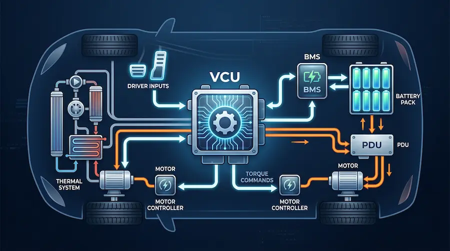
A Vehicle Control Unit (VCU) is the master supervisory controller in an electric vehicle (EV). It is an electronic control unit that manages and coordinates the powertrain, the Battery Management System (BMS), the High-Voltage Power Distribution Unit (PDU), and motor controllers. The VCU interprets driver inputs, executes torque commands, manages thermal systems, and ensures functional safety across the entire vehicle network.
If you want to understand exactly how a VCU dictates vehicle behavior, how it differs from a standard ECU, and how to successfully design and test one for demanding environments, you are in the right place. Let’s dive deep into engineering.
What Is A VCU?
In the simplest terms, the VCU is the master computer of an electric vehicle.
In traditional internal combustion engine (ICE) vehicles, the Engine Control Unit (ECU) manages fuel injection and ignition. But EVs don’t have engines. Instead, they rely on complex high-voltage electrical systems that demand split-second coordination.
The VCU steps into this role as the ultimate decision-maker. It doesn’t directly spin the motor or balance the battery cells itself. Instead, it acts as a conductor of an orchestra. It tells the motor controller how much torque to apply, it asks the battery if it can safely deliver that power, and it commands the cooling system to keep temperatures in check.
What Does VCU Stand For In Electrical?
VCU stands for Vehicle Control Unit.
In electrical and systems engineering, the VCU is classified as a specialized embedded electronic control unit. It is packed with automotive-grade microprocessors, memory chips, and multiple Input/Output (I/O) interfaces.
Electrically, the VCU serves as the central gateway for the vehicle’s communication networks. It connects directly to various Controller Area Network (CAN) buses, Local Interconnect Network (LIN) buses, and sometimes Automotive Ethernet.
This allows it to process hundreds of electrical signals per second—ranging from a simple 5V analog signal from your accelerator pedal to complex digital CAN messages from the high-voltage battery.
What Is The Role Of VCU In EV?
The role of the VCU is to guarantee that the vehicle operates exactly as the driver intends, while keeping all electrical and mechanical systems within strict safety limits.
Battery projects often fail at the integration stage—not because components are unavailable, but because mechanical, thermal, electrical, and control systems are not developed as one coordinated solution 8. The VCU is the component that brings this coordinated solution to life.

Here are the primary roles the VCU plays:
Torque Master: It decides how much power the vehicle should output based on pedal position, current speed, and driving mode.
State Machine Manager: It governs the vehicle states (e.g., Key OFF, Accessory, Pre-charge, Drive, Park, Fault).
Safety Supervisor: It monitors the entire system for faults (like a loss of isolation or over-temperature) and triggers safe-shutdown procedures to prevent catastrophic failures.
What Is The Function Of The VCU?
To understand the sheer power of the VCU, we need to look at its specific functions.
1. Powertrain Coordination and Torque Mapping
When you press the accelerator, you aren’t directly feeding voltage to the motor. You are sending an analog signal to the VCU. The VCU calculates the requested torque, checks it against the current vehicle speed, and sends a digital command to the Motor Control Unit (MCU) to spin the wheels.
2. High-Voltage System Management
This is a critical function. The VCU controls the PDU/HV Control Box (Power Distribution Unit). Before the vehicle can drive, the VCU commands the PDU to execute a highly controlled “pre-charge sequence.” It closes specific high-voltage contactors in a precise order to prevent massive inrush currents from damaging the inverter.
3. Energy and Regenerative Braking Management
When you lift your foot off the accelerator, the VCU calculates how much kinetic energy can be recaptured. It communicates with the BMS (Battery Management System) to check the battery’s maximum charge limits, then commands the motor to act as a generator, pushing energy back into the lithium-ion battery pack.
4. Thermal Management
Tier-1 cell manufacturers will sell you raw modules, but they leave you with a massive engineering headache: How do you cool them? The VCU handles this logic. It monitors temperatures from the BMS and MCU, and commands water pumps, chiller valves, and radiator fans to maintain optimal fluid dynamics in the liquid cooling loop.
What Is The VCU Coordinate In An EV?
When we talk about the VCU “coordinate” (or coordination), we are referring to its position as the central node in the vehicle’s electrical topology.
Think of a modern EV as a localized internet. The VCU is the primary router.

It coordinates the holy trinity of the EV powertrain:
The Lithium-ion Battery Pack (via BMS): The VCU constantly polls the BMS for the State of
Charge (SOC), State of Health (SOH), and instantaneous discharge/charge current limits.
The Motor Control Unit (MCU): The VCU dictates the torque requests and monitors motor RPM and temperature.
The PDU/HV Control Box: The VCU manages the physical routing of high-voltage DC power by opening and closing contactors inside the PDU.
If the BMS detects a cell over-voltage, it doesn’t shut down the car abruptly. It sends a warning to the VCU. The VCU coordinates a graceful derating of motor power, turning on a warning light on the dashboard, and opening the PDU contactors safely.
How Does The VCU Work For EVs?
The VCU operates on a continuous feedback loop governed by a Real-Time Operating System (RTOS). It works in three distinct phases: Inputs, Processing, and Outputs.
Step 1: Gathering Inputs
The VCU reads physical hardware sensors directly. This includes the accelerator pedal position, brake pressure sensors, and gear selector switches (PRND). Simultaneously, it reads CAN bus messages from the BMS, MCU, and ABS systems.
Step 2: Processing and Logic
Inside the VCU’s microcontroller, complex algorithms (often developed in C/C++ or via Model-Based Design tools like Simulink) process this data. The software evaluates the driver’s request against the vehicle’s current physical limitations.
For example, if you demand 100% throttle, but the BMS reports the lithium-ion battery pack is at 5% SOC and running hot, the VCU logic intervenes. It overrides your request and limits the torque to protect the battery chemistry.
Step 3: Executing Outputs
Once the logic is resolved, the VCU sends out command signals. It fires low-side drivers to trigger cooling pumps, sends CAN messages to the MCU for exact torque delivery, and broadcasts vehicle speed to the dashboard display.

This entire three-step loop happens in milliseconds, continuously, as long as the vehicle is awake.
What Does The VCU Consist Of For An EV?
A VCU is a masterpiece of both hardware and software engineering. Here is what is actually inside that rugged metal box.
The Hardware
Microcontroller Unit (MCU): The silicon brain. Usually a 32-bit automotive-grade multi-core processor (like the Infineon AURIX or NXP S32K series) designed for functional safety.
Power Supply Circuit: Steps down the vehicle’s 12V or 24V system to the precise 5V or 3.3V needed for the microchips.
Communication Transceivers: Hardware chips that translate the microprocessor’s logic into physical CAN, LIN, or Ethernet signals.
I/O Interfaces: High-side and low-side drivers for switching relays, and Analog-to-Digital Converters (ADCs) for reading sensor voltages.
Enclosure: A ruggedized, heavily sealed metal housing. For heavy-duty or marine applications, these enclosures must be engineered to IP67+ standards to resist water, dust, and extreme vibration.
The Software
Basic Software (BSW): The foundational layer that handles memory management, I/O protocols, and communication stacks (often built on the AUTOSAR standard).
Application Layer: The actual vehicle control strategy. This is where your custom torque maps, thermal management logic, and state machines live.

What Are The Benefits Of The VCU?
Why not just let the motor controller and the battery talk to each other directly? Why add a VCU?
Here is why relying on a VCU is non-negotiable for modern electric platforms:
Centralized Functional Safety: If a component fails, the VCU acts as a centralized fail-safe. It ensures compliance with strict safety standards like ISO 26262.
Optimized Range and Efficiency: By controlling the exact interplay between the battery and the motor, the VCU maximizes regenerative braking and minimizes wasted energy, directly extending vehicle range.
Simplified Architecture: Instead of complex point-to-point wiring between every component, the VCU centralizes the logic. You run a single CAN bus network, vastly reducing wire harness weight and complexity.
Custom Vehicle Character: The VCU software determines how the vehicle feels. You can program one VCU map for an aggressive sports car feel, and another for a smooth, high-torque electric tractor—using the exact same battery and motor.
What Are The Differences Between ECU And VCU?
This is a common point of confusion.
ECU (Electronic Control Unit) is a generic umbrella term. Any embedded computer in a vehicle is an ECU. Your door locks have an ECU. The BMS is an ECU. The airbag controller is an ECU.
VCU (Vehicle Control Unit) is a highly specific type of ECU. It sits at the very top of the hierarchy.
Think of it like a corporate structure. The ECUs are the department managers (the BMS manages the battery; the MCU manages the motor). The VCU is the CEO. It doesn’t micromanage the individual battery cells, but it takes reports from the BMS and makes strategic decisions for the whole vehicle.

How To Design A VCU For EVs?
Designing a VCU is not a plug-and-play affair, especially for demanding commercial applications. We work with customers as an engineering-driven integration partner, and projects typically begin with a review of the application, operating profile, packaging constraints, electrical targets, and compliance needs.
Here is the standard engineering process for VCU design:
1. Requirements Engineering
You must define every single vehicle state, fault condition, and performance metric. What happens if the CAN bus line to the PDU is cut? What happens if the driver shifts into Reverse while traveling 50 mph? The VCU must have a predefined answer for everything.
2. Model-Based Design (MBD)
Instead of hand-coding C++, engineers use software like MATLAB and Simulink to visually map out control logic. This allows teams to simulate vehicle behavior in a virtual environment before ever building a prototype.
3. Hardware-Software Integration
This is where projects often hit a wall. You might procure a great lithium-ion battery pack and a smart BMS, but getting your VCU to interpret their specific CAN matrices is incredibly difficult.
This is exactly where Astraion Dynamics steps in. Tier-1 cell manufacturers are built for massive standard volume, often rejecting deep customization for off-highway, marine, or specialized commercial fleets. They sell you raw modules and leave you to figure out how to make them talk to your vehicle.
Our defining strength is our transparent “Bring Your Own Cells/Modules” partnership model. We handle the deep engineering ecosystem. Our in-house engineering team designs intelligent BMS architectures, high-voltage PDUs, and handles the complex VCU communication so you don’t have to.
How To Test The VCU For EVs?
You cannot simply plug a newly programmed VCU into a multi-million-dollar electric mining truck and hope for the best. Testing must be rigorous and staged.

1. Software-in-the-Loop (SIL)
The control logic is tested in a purely virtual environment to ensure the mathematical algorithms behave correctly.
2. Hardware-in-the-Loop (HIL)
This is a critical step. The physical VCU hardware is plugged into a HIL simulator—a powerful computer that mimics the vehicle. The simulator feeds fake sensor data (like a simulated accelerator pedal or a fake BMS CAN signal) into the VCU.
The VCU thinks it is driving a real vehicle. We monitor its outputs to the “PDU” and “Motor” to ensure it behaves safely, without ever exposing engineers to actual high voltage.
3. System Commissioning and Vehicle Testing
Finally, the VCU is integrated into the real vehicle. Heavy trucks have high demands for battery pack durability, liquid cooling, and high-voltage integration. At this stage, we calibrate the torque maps on a dynamometer and ensure flawless UN38.3 / ECE R100.3 homologation. We stay involved until the system is tested, integrated, and ready to work in the field.
Conclusion
The Vehicle Control Unit (VCU) is the undisputed brain of your EV. It translates driver intent into physical motion, acts as the ultimate safety supervisor, and forces your lithium-ion battery pack, BMS, and PDU/HV Control Box to work together as a seamless, high-performance powertrain.
Without a well-engineered VCU, you just have a very expensive pile of uncoordinated electronics.
If you are a Chief Engineer, or Program Manager feeling the pain of system integration, you don’t have to navigate this alone. Astraion Dynamics is a turnkey integration partner for lithium-ion battery systems in heavy-duty, marine, and off-highway applications.

We transform your procured raw modules into a rugged, fully certified, plug-and-play energy system. You control the chemistry, we master the engineering.
If you’re ready to shorten your development cycles and bring your battery-powered platforms into operation with greater confidence, contact our integration team today. Let’s make your vehicle run flawlessly.
