

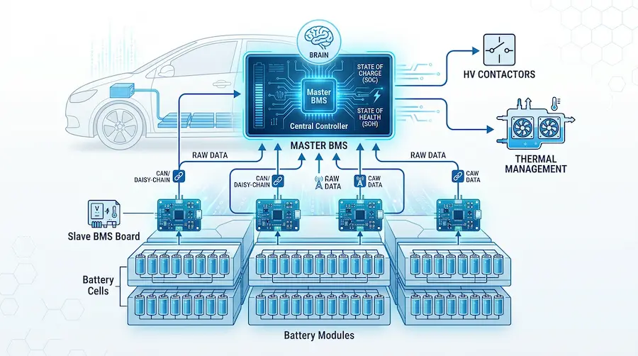
Hi, I’m a battery systems engineer. If you build heavy-duty EVs or ESS, you’ve likely hit a wall with battery management. Today, I’m breaking down the Master BMS vs. Slave BMS architecture. Did you know distributed BMS setups can reduce high-voltage wiring weight by over 30% in commercial trucks?
A Master BMS is the central brain of a battery pack, computing SOC/SOH, controlling thermal management, and switching high-voltage contactors. A Slave BMS is a local module board that measures individual cell voltages and temperatures, sending this raw data to the Master via isolated communication links like CAN or daisy-chain networks.
Want to know exactly how these two components work together to prevent thermal runaway? Let’s dive deep into the architecture that keeps modern mobility platforms safe.
What is the Master BMS for EVs?
Think of the Master Battery Management System (often called the BMU or Battery Management Unit) as the CEO of your lithium-ion battery pack system.
It doesn’t get its hands dirty measuring every single battery cell. Instead, it looks at the big picture.
The Master BMS is the central processing unit that receives raw data from the lower-level components and makes critical, split-second decisions. It is responsible for calculating complex algorithms, such as State of Charge (SOC), State of Health (SOH), and State of Power (SOP).
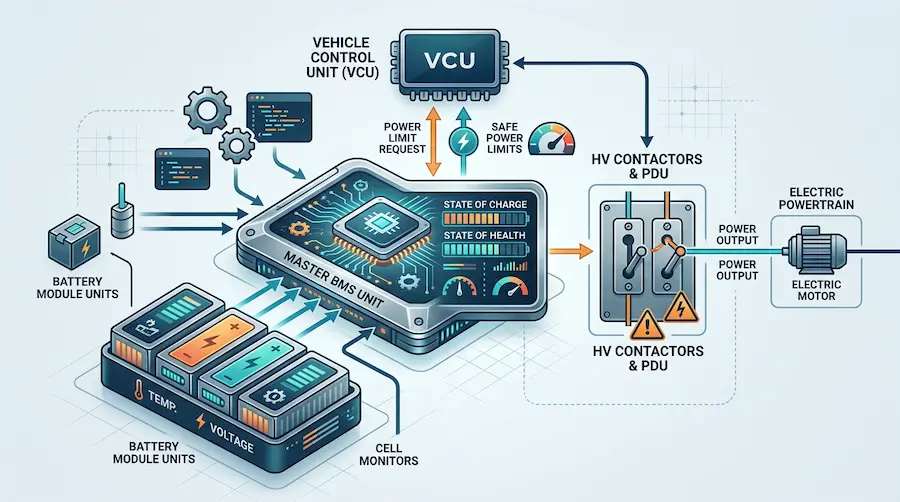
If you are a CTO or a Vehicle Integration Engineer, you know that the Master BMS is your battery’s main interface with the rest of the machine. It communicates directly with the Vehicle Control Unit (VCU).
When the driver hits the accelerator in a heavy-duty electric truck, the VCU asks the Master BMS, “How much power can you give me right now?” The Master BMS instantly calculates the safe discharge limit based on real-time cell temperatures and voltages, and replies with a hard limit to prevent battery degradation.
Furthermore, the Master BMS controls the High-Voltage (HV) Power Distribution Unit (PDU). It commands the main contactors to open or close, physically connecting or disconnecting the battery from the powertrain. If things go wrong, the Master BMS is the ultimate failsafe that shuts the system down.
What Is the Slave BMS for EVs?
If the Master BMS is the CEO, the Slave BMS (often called the CMU, Cell Management Unit, or Local Energy Board) represents your frontline workers.
A Slave BMS is a smaller, highly specialized circuit board that sits directly on top of or physically right next to the battery modules.
When OEMs utilize a “Bring Your Own Cells/Modules” partnership model, the first layer of engineering involves integrating these Slave BMS units directly onto those raw modules.
The primary job of the Slave BMS is data collection. It features highly sensitive Analog Front End (AFE) chips that measure the exact voltage of every single cell in its module (often down to a 1mV resolution). It also reads the NTC thermistors to monitor localized temperatures.
But it doesn’t just collect data. The Slave BMS also executes physical cell balancing.
Lithium-ion cells naturally drift out of balance over time. When the Master BMS detects that one cell has a higher voltage than the rest, it sends a command down to the Slave BMS. The Slave then activates a balancing circuit (usually passive balancing via a resistor) to bleed off that excess energy as heat, bringing the cells back into perfect harmony.
What Is the Use of the Master BMS and Slave BMS?
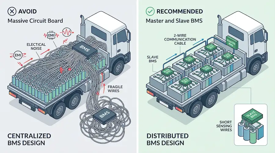
Why do we split the BMS into a Master and multiple Slaves? Why not just build one massive circuit board to manage everything?
The short answer: Scalability and Wiring.
In a standard 12V lead-acid battery, you only have a few cells. But in modern electric trucks and heavy-duty vehicles, battery packs operate at 400V or even 800V. These high-voltage systems require 100 to 200 lithium-ion cells wired in series. Energy Storage Systems (ESS) can have thousands of cells.
If you tried to wire every single cell directly to one central BMS, you would end up with hundreds of long, fragile voltage-sensing wires running back and forth across a massive battery pack.
This creates a massive engineering headache. Long wires act like antennas, picking up Electromagnetic Interference (EMI) from the vehicle’s electric motor, which corrupts the voltage readings. Plus, routing hundreds of wires increases the risk of a short circuit if the insulation rubs off from vehicle vibration.
By splitting the system, you only run short sensing wires from the cells to the local Slave BMS. Then, the Slave BMS sends digital data over a simple, robust 2-wire communication cable back to the Master BMS.
This distributed architecture is absolutely vital for Heavy-duty commercial trucks, which have extreme demands for battery pack durability and high-voltage integration.
How Does Master BMS and Slave BMS Work?
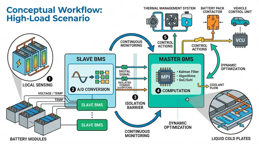
The workflow between these two components is a beautiful example of engineering synchronization. Let’s walk through exactly how they work together during a high-stress scenario—like an electric mining truck carrying a heavy load up a steep grade.
Step 1: Local Sensing. As the truck climbs, the battery discharges rapidly. The Slave BMS units attached to the battery modules continuously sample the voltage and temperature of their assigned cells.
Step 2: Analog-to-Digital Conversion. The AFE chip on the Slave BMS converts these analog voltage and temperature readings into robust digital signals.
Step 3: Isolated Communication. The Slave BMS transmits this digital data packet to the Master BMS. To ensure safety and prevent high-voltage ground loops, this communication (usually via isoSPI or CAN bus) passes through an isolation barrier (like a digital isolator or transformer).
Step 4: Computation. The Master BMS receives the data packet. Its powerful 32-bit microcontroller runs a Kalman filter algorithm to update the State of Charge. It notices that the module is heating up faster than the rest.
Step 5: Action and Control. The Master BMS immediately takes action. It commands the vehicle’s thermal management system to increase the flow rate of the liquid coolant through the precision liquid cold plates.
Because mechanical, thermal, electrical, and control systems are developed as one coordinated solution, the battery pack stays within its safe operating temperature without interrupting the vehicle’s operation.
What Does the Master BMS and Slave BMS Consist Of?
To understand how they perform these feats, you need to look at the hardware layer.
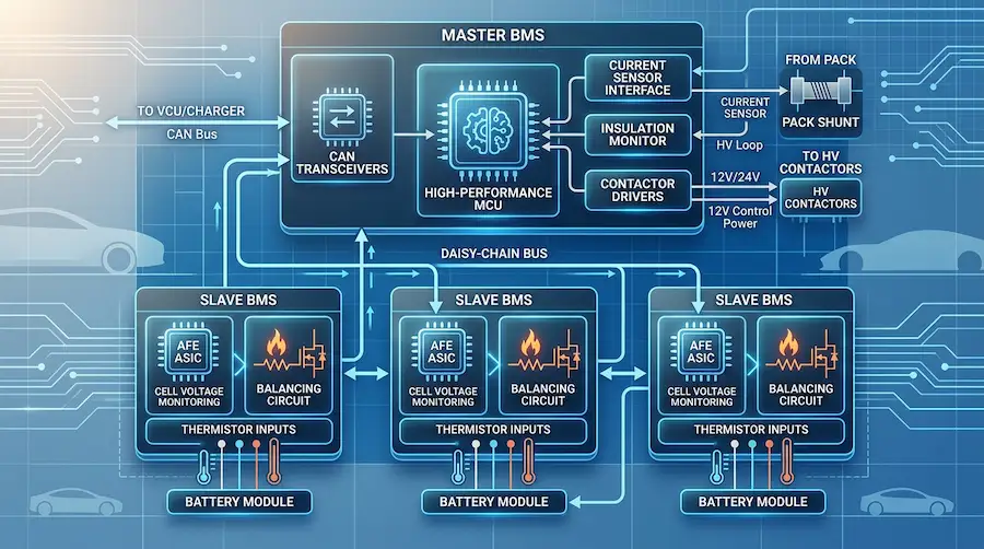
The Master BMS typically consists of:
A High-Performance MCU (Microcontroller Unit): The central brain (e.g., ASIL-D rated chips from Infineon or NXP) that handles heavy math and logic.
CAN Transceivers: To communicate with the VCU, chargers, and the Slave boards.
Current Sensor Interface: Reads data from Hall-effect sensors or precision shunts to measure total pack current.
Insulation Monitoring Circuit: Continuously checks for high-voltage leaks to the vehicle chassis.
Contactor Drivers: Low-side or high-side switches that supply the 12V/24V power needed to close the massive high-voltage contactors inside the PDU.
The Slave BMS typically consists of:
AFE (Analog Front End) ASICs: Specialized chips designed specifically to read lithium-ion cell voltages with extreme accuracy.
Balancing Resistors & MOSFETs: Small components that switch on to burn off excess voltage from overcharged cells.
Thermistor Inputs: Channels to connect temperature probes.
Daisy-Chain Communication Ports: Allows multiple Slave boards to be wired in a series loop (daisy-chain), passing data sequentially up to the Master.
What Are the Differences Between the Master BMS and Slave BMS?
If you are a Purchasing Manager or Strategic Sourcing Lead comparing supplier quotes, you need to understand the distinct differences between these two components.
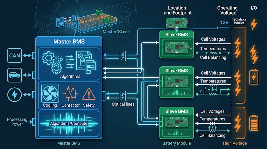
1. Location and Physical Footprint:
The Master BMS is usually a single, enclosed unit housed near the high-voltage distribution box or externally on the pack casing. Slave BMS units are bare circuit boards mounted directly inside the battery enclosure, bolted directly onto the cell module busbars.
2. Processing Power:
The Master BMS requires high compute power to run complex algorithms (SOC/SOH) and manage system-level safety protocols. The Slave BMS requires very little compute power; its main job is precise analog measurement and simple command execution.
3. Operating Voltage:
The Master BMS usually operates on the vehicle’s low-voltage system (12V or 24V), safely isolated from the battery’s high voltage. The Slave BMS, however, references the high voltage of the modules it is attached to. It literally “floats” at high voltage, which is why isolated communication is critical.
4. I/O (Inputs/Outputs):
The Master has system-level I/O (contactor control, crash sensor inputs, liquid cooling pump control). The Slave only has local I/O (cell voltage taps, local NTC thermistors, and balancing circuits).
What Are the Advantages and Disadvantages of the Master BMS and Slave BMS?
Like any engineering choice, the distributed Master/Slave architecture has pros and cons.
Advantages:
Unmatched Scalability: Need to make a bigger battery pack? Just add more battery modules and daisy-chain a few more Slave BMS units. You don’t need to redesign the Master.
Reduced Wiring Harness Weight: Eliminates the massive bundle of sensing wires, significantly reducing vehicle weight and assembly complexity.
Enhanced Safety: Short sensing wires reduce the risk of physical shorts. Improved EMI immunity means fewer false voltage readings.
Easier Maintenance: If one module fails in the field, a technician can replace just that module and its attached Slave BMS, rather than ripping out the entire pack wiring.
Disadvantages:
Higher Component Cost: You are buying multiple printed circuit boards (PCBs) instead of just one.
Software Complexity: Writing the software to manage communication across dozens of Slave boards with microsecond timing is a massive engineering headache.
Communication Latency Risk: If the daisy-chain network gets interrupted, the Master loses visibility of the cells.
This is exactly why battery projects often fail at the integration stage—mechanical, electrical, and control systems must be developed as one coordinated solution to overcome these software and communication hurdles.
In Which System Can the Master BMS and Slave BMS Work Together?
The Master/Slave architecture isn’t just a luxury; for many applications, it is a strict technical necessity. We see this architecture dominating several key sectors:
Electric Truck and Heavy-Duty Vehicles:
Heavy trucks require massive battery packs to move heavy loads. They demand high battery pack durability, liquid cooling, and high-voltage integration. The distributed BMS allows the pack to be spread across different physical locations on the chassis (e.g., behind the cab and along the frame rails) while a single Master BMS coordinates them all.
Electric Boat and Marine Vessels:
Electric ferries and boats have stringent requirements for waterproofing and system integration. By using a Master/Slave setup, the high-voltage battery modules and their Slave boards can be sealed inside rugged IP67+ aluminum enclosures, while the Master BMS communicates safely with the vessel’s main helm control.
Energy Storage Systems (ESS):
ESS projects require large-scale battery packs and extensive PDUs/BMS. A grid-scale battery container might have 20 racks of batteries. Each rack has multiple Slave BMS units, all reporting up to a Master BMS (and sometimes a “Grandmaster” BMS for the whole container).
Off-Highway and Mining Equipment:
Battery electric mining vehicles demand highly reliable, explosion-proof, and heavy-duty battery systems. The modular nature of the Slave BMS allows engineers to design uniquely shaped, ruggedized battery packs that fit into the awkward, constrained spaces of construction and agricultural machinery.
If you are developing any of these battery-powered platforms for demanding applications, you need a system that is engineered around the real requirements of the vehicle, vessel, or machine.
Conclusion
Master and Slave BMS architectures are the backbone of modern, high-voltage lithium-ion battery packs. They provide the safety, scalability, and precision required to push the boundaries of heavy-duty commercial EVs and ESS platforms. But buying the hardware is only half the battle; integrating them flawlessly into your mechanical and thermal constraints is where the real magic happens.
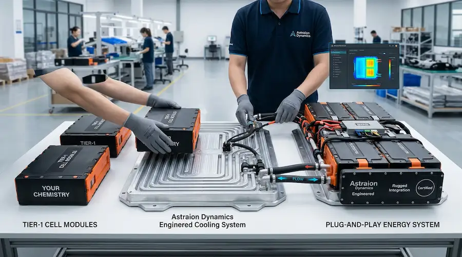
If your engineering team is tired of dealing with massive integration headaches from raw cell manufacturers, we can help. At Astraion Dynamics, our business model is simple: You control the chemistry, we master the engineering. We transform your procured raw modules into a rugged, fully certified, plug-and-play energy system.
Ready to shorten your development cycle and bring your platform to market with confidence? Contact our engineering team today to review your application profile and discover how our turnkey BMS and liquid cooling integration can upgrade your next project.
