BMS Selection and Integration | EV & Energy Storage Battery Systems
Solution · System-Level Battery Engineering

BMS Selection and Integration Battery Systems

System-level BMS integration engineered for safety, reliability, and seamless compatibility with battery enclosures, cooling systems, and power electronics interfaces.

Integration Scope
Mech + Thermal
Enclosure + cooling interfaces
Reliability
Sealing Ready
IP67-oriented design options
Manufacturing
DFM Driven
Repeatable assembly at scale
BMS Integration Map
Enclosure · Cooling · Cabling
Hero Image Placeholder
System Diagram / Render
Recommended: clean 3D render showing BMS location inside enclosure + cable routing + cooling plate.
Enclosure
Mounting zone & sealing
Thermal
Heat paths & isolation
Electrical
Harness & connectors

What Is BMS Selection and Integration

Battery Management System (BMS) selection and integration is a critical step in building safe and reliable battery systems. It involves choosing the appropriate BMS hardware and ensuring mechanical, thermal, electrical, and communication compatibility within the complete battery system.

We support BMS integration as part of a complete battery engineering process—never treating BMS as an isolated electronic component. If you are building a sealed pack, start from the enclosure: Battery Pack Enclosures & Trays.

System compatibility
BMS + enclosure + cooling + harness
Risk reduction
Prevent rework before validation & certification
Image Placeholder
BMS Integration Overview
Suggested image: clean schematic showing BMS + connectors + harness routing inside an aluminum battery enclosure.
Mechanical
Mounting
Thermal
Heat Paths
Electrical
Cabling

Our Role in BMS Integration

We focus on system-level integration—working closely with OEMs, battery integrators, and BMS suppliers to ensure the chosen BMS can be reliably installed and protected inside the physical battery system.

Mechanical integration
Mounting zones, brackets, accessibility for service
Thermal compatibility
Heat paths, isolation, proximity to cooling plates
Electrical layout coordination
Harness routing, connector interfaces, strain relief
Sealing & protection
Ingress protection strategy at enclosure level
Assembly support
Sequence planning, manufacturability & repeatability
Validation support
Fit checks, sealing interface verification, traceability
Common integration foundation
Most BMS issues become mechanical issues—space, sealing, cable exits, vibration, and heat. We solve those together with your enclosure and cooling design.

BMS Selection Considerations

We assist customers in evaluating BMS options with the end integration in mind—so the chosen BMS fits the enclosure, cooling, sealing, and harness strategy.

Chemistry & configuration
Pack architecture, cell count, topology
Voltage / current range
Power targets, safety margins
Monitoring architecture
Distributed vs centralized, harness complexity
Communication protocols
CAN, RS485, and integration constraints
Environment & protection
Ingress, condensation, chemical exposure
Standards & certification
Safety compliance planning
System fit-first mindset Harness & serviceability Sealing & thermal constraints
Image Placeholder
BMS Selection Checklist
Suggested image: clean checklist graphic + protocol icons (CAN/RS485).

Mechanical Integration into Battery Enclosures

BMS units must be mechanically protected and properly mounted to withstand real duty cycles in EV and industrial environments.

We support
  • Dedicated BMS mounting zones inside battery enclosures
  • CNC-machined mounting features and brackets
  • Vibration-resistant structural design
  • Accessibility for service and diagnostics
Image Placeholder
BMS Mounting Zone
Suggested image: enclosure interior showing mounting bosses/brackets + connector clearance.
Design focus
Protection + Accessibility
Diagnostics access without compromising sealing
Mounting details
Fasteners & Standoffs
Clearance, insulation, and service tools

Thermal Integration with Cooling Systems

Thermal behavior of BMS electronics is often overlooked. We design battery systems where BMS integration considers heat dissipation, isolation, and stable operating temperature under continuous load.

Integration considerations
  • Proximity to liquid cooling plates
  • Heat dissipation paths
  • Thermal isolation from hot zones
  • Stable temperature under load
Recommended references
  • Interface flatness planning
  • Thermal pad/contact strategy
  • Module-to-plate alignment
Image layout (thermal)
Image Placeholder
BMS Thermal Layout
Suggested image: 3D render showing BMS placement relative to cooling plate & hot zones.
Heat dissipation paths
Plan conductive paths + avoid trapped hot air
Isolation strategy
Separate BMS from high-temp components
Request Thermal Integration Review

Sealing and Environmental Protection

BMS components are sensitive to moisture, dust, and contamination. We integrate BMS with an enclosure-level sealing mindset—especially for outdoor and heavy-duty use cases.

Our approach includes
  • IP67 sealing design at enclosure level
  • Gasket and O-ring groove machining
  • Controlled cable and connector sealing interfaces
  • Protection against condensation and ingress
Image layout (sealing)
Image Placeholder
Connector + Cable Sealing
Suggested image: close-up of cable exit sealing or connector panel interface.
Groove machining
Gasket / O-ring groove geometry control
Ingress planning
Dust + water spray + condensation considerations
Explore Battery Enclosures & Trays

Electrical Interface & Cable Management

We coordinate mechanical design with electrical integration requirements to reduce assembly errors and improve serviceability.

Support includes
  • Cable routing and strain relief design
  • Connector mounting interfaces
  • Space allocation for wiring harnesses
  • Grounding and isolation considerations
Image Placeholder
Harness Routing Layout
Suggested image: cable routing diagram with strain relief points.
Buyer-friendly deliverables
Useful during RFQ and build readiness
Connector panel plan
Mounting, sealing, and service access
Harness constraints
Bend radius, routing channels, fixation points
Assembly notes
Sequence to prevent pinches and rework

Structural Protection & Vibration Resistance

In mobile applications, BMS must withstand vibration and shock. We design mounting structures that keep electronics protected through real duty cycles.

Reinforced mounting
Stiff supports, controlled fastener strategy
Anti-vibration features
Isolation, damping options, fatigue planning
Impact avoidance
Placement away from high-impact zones
Recommended image module
Image Placeholder
Vibration-Ready Mounting Detail
Suggested image: mounting bracket detail or test fixture photo.

Manufacturing & Assembly Support

We support BMS integration through the manufacturing phase to make it manufacturable and repeatable at scale.

Recommended image module
Show the assembly sequence (simple 3-step visual) to build buyer confidence.
Step 1: Mount BMS Step 2: Route Harness Step 3: Seal & Verify
Image Placeholder
Assembly Sequence Visual
Suggested image: 3-panel graphic (mount → route → seal).

Quality Control & Validation

BMS integration quality is validated through dimensional inspection of mounting features, verification of sealing interfaces, assembly checks, traceability, and coordination with system-level testing.

Validation workflow
  • Mounting feature inspection (fit, clearances)
  • Sealing interface verification
  • Assembly checks and traceability
  • Coordination with system-level tests
Dimensional control Sealing evidence Build traceability
Image layout (validation)
Image Placeholder
Inspection & Verification
Suggested image: CMM or dimensional inspection scene / checklist.
Sealing interface check
Confirm cable exits & connector sealing strategy
Assembly audit
Verify strain relief and harness routing
Request Validation Readiness Review

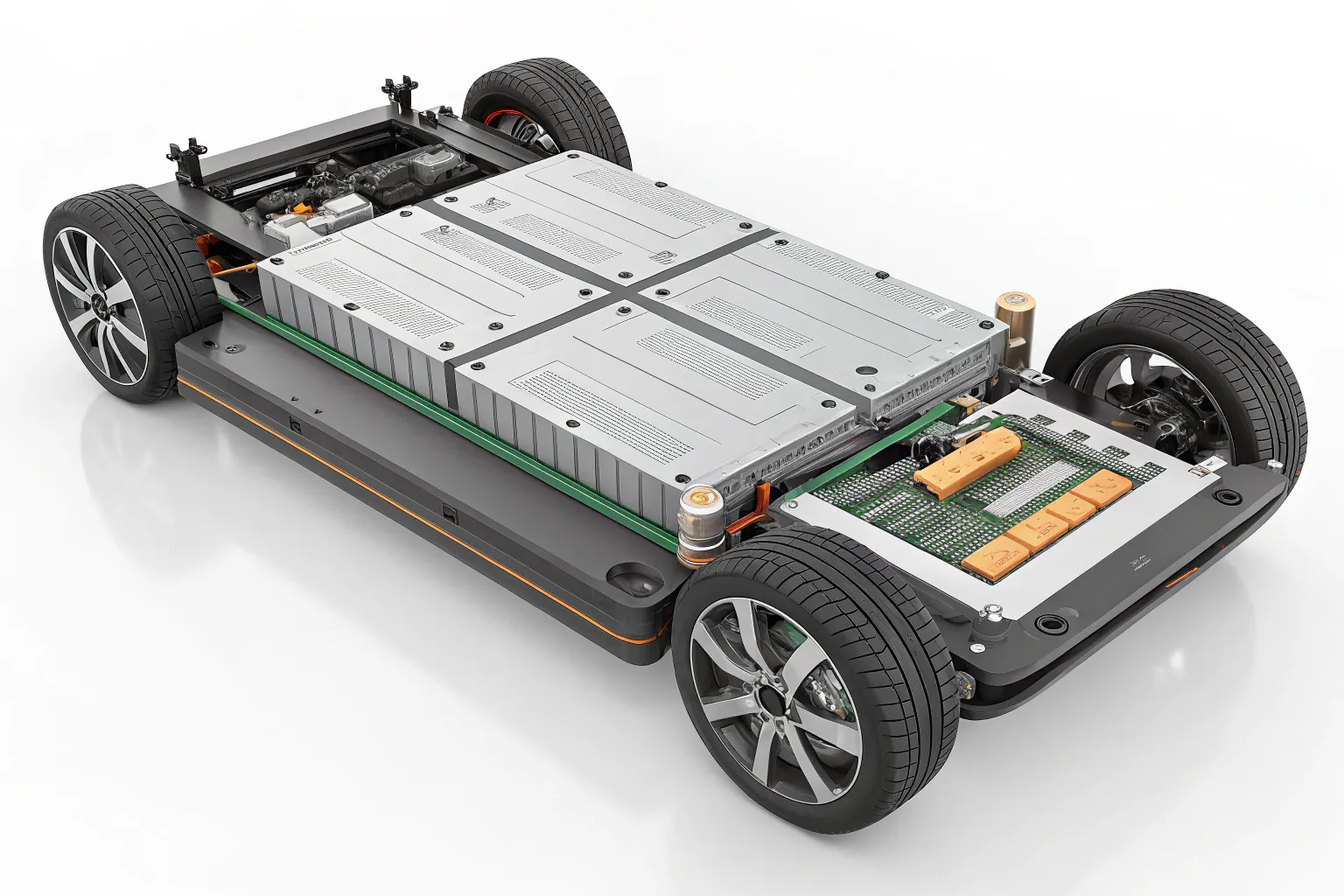
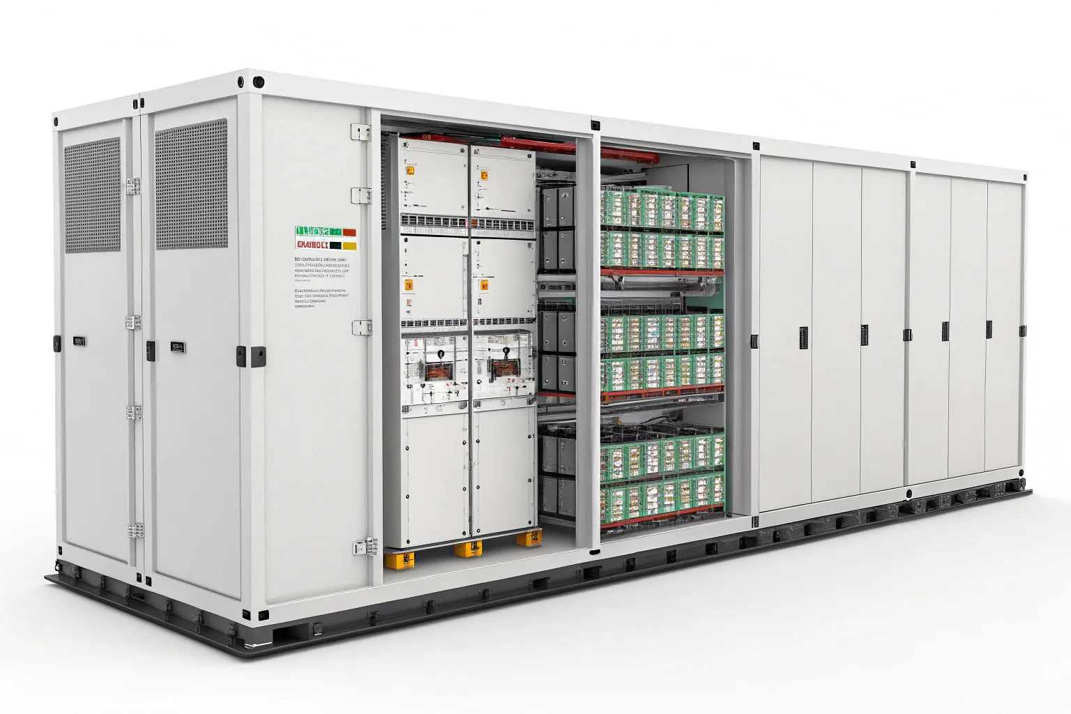
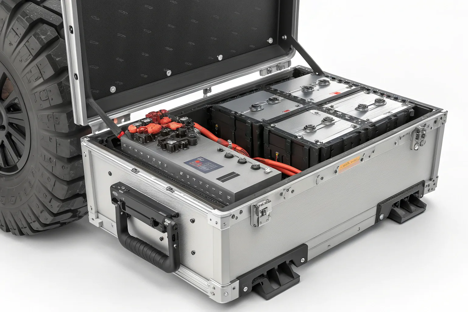
Typical Application Scenarios

BMS selection and integration support commonly applies to EV, ESS, and harsh-environment platforms where sealing, vibration, and thermal behavior directly impact uptime.

Project Integration Examples

Representative integration patterns (use your real case photos/renders here).

EV Pack with Integrated BMS
EV Battery Pack with Integrated BMS
  • BMS mounted inside sealed aluminum enclosure
  • Connector sealing interfaces planned
  • Cooling interface compatibility
ESS BMS Integration
ESS Battery Module System
  • Centralized BMS integration concept
  • Modular enclosure packaging strategy
  • Service access planning
Off-Highway BMS
Off-Highway Battery System
  • Vibration-resistant BMS mounting
  • Enhanced sealing design
  • Harness strain relief and routing
Related pages
If your project is enclosure/cooling-driven, start here.

Why Choose Us for BMS Integration

Built around what OEM engineering and procurement teams care about: integration reliability, sealing confidence, manufacturable design, and fast technical response.

System-level battery engineering mindset
BMS + enclosure + cooling + harness, designed as one system
Strong mechanical and thermal integration capability
Placement, heat paths, service access
Experience with sealed enclosures and cooling systems
IP-oriented design options + practical sealing interfaces
Manufacturing-oriented design approach
Repeatable assembly and reduced integration risk
Support from prototype to mass production
DFM → prototype → pilot → stable SOP
Technical Fit Check
Send these, we’ll respond faster
1) System drawings
STEP / DWG / PDF
2) Electrical requirements
Voltage/current range, protocols (CAN/RS485)
3) Environment + sealing target
Ingress risk, condensation, target IP level

Contact & Technical Consultation

Discuss your BMS integration requirements with our engineering team. Upload your system drawings (STEP / DWG / PDF) for technical review.

Email
andrew@sannytelecom.com
Fast response for technical support & integration review
Send Your Request
Attach: STEP / DWG / PDF · Include: chemistry/config, voltage/current, protocol, sealing target, environment, and expected volume/timeline.
Tip: Put “IP target” / “Protocol (CAN/RS485)” / “Cooling plate type” in the email subject to speed up engineering routing.