

If you are building a heavy-duty EV, marine vessel, or off-highway machine, getting your battery chemistry right is only half the battle. The real headache usually starts when you try to route hundreds of volts safely without catastrophic failures—and that is exactly where a properly engineered PDU comes in.
A Power Distribution Unit (PDU) in a battery pack system is a centralized high-voltage electrical box that connects, manages, and protects the flow of electrical current between the battery modules and the vehicle’s powertrain. It houses safety-critical components like high-voltage contactors, fuses, pre-charge resistors, and insulation monitoring systems.
Want to know how to design, integrate, and source a bulletproof PDU that won’t hold up your vehicle’s commissioning schedule? Let’s dive right into the details.
What Is A PDU Power Distribution Unit?
A Power Distribution Unit (PDU), often referred to as a High-Voltage Box (HV Box) or Battery Disconnect Unit (BDU), is the electrical gatekeeper of your entire energy storage system.
Look: tier-1 cell manufacturers will gladly sell you thousands of raw battery modules, but they leave you with a massive engineering headache when it comes to safely managing the power those modules output. The PDU is the solution to that headache.
It acts as the central switchboard for the high-voltage (HV) DC power. Whenever the driver turns the key, the vehicle’s powertrain doesn’t just connect to the battery directly. Instead, the vehicle control unit talks to the PDU, which runs a series of safety checks before physically closing the circuits to let the power flow.
If there is a short circuit, an overcurrent event, or a thermal anomaly, the PDU is the component responsible for instantly cutting the power to prevent thermal runaway or electrical fires.

What Are The Purposes Of The PDU In A Battery Pack System?
When engineering managers approach us for battery system integration, they often underestimate the heavy lifting the PDU does.
Here is exactly what a PDU is designed to achieve:
High-Voltage Isolation: It physically disconnects the high-voltage battery from the rest of the vehicle when the system is turned off or during an emergency.
Overcurrent Protection: It acts as the ultimate fail-safe. If your motor controller malfunctions and draws a massive spike in current, the PDU severs the connection to protect the battery cells.
Safe System Start-Up: It manages the initial surge of electricity when the vehicle is turned on, protecting downstream capacitors from exploding.
Power Branching: It doesn’t just power the main electric traction motor. A PDU also distributes high-voltage power to auxiliary systems like the electric AC compressor, PTC cabin heater, and DC-DC converters.
Diagnostic Monitoring: Modern PDUs constantly monitor voltage levels and current flow, feeding this critical telemetry back to the vehicle’s central computer.
How Does The PDU Work In A Battery Pack System?
Understanding how a PDU operates requires looking at the vehicle’s start-up sequence. It is not as simple as flipping a light switch.
Here is the step-by-step process of how a PDU functions in the real world:

Step 1: The Wake-Up Call
When the operator turns on the vehicle, the Vehicle Control Unit (VCU) sends a low-voltage signal to the Battery Management System (BMS). The BMS runs a split-second diagnostic check on the battery modules.
Step 2: The Pre-Charge Phase
If the system is healthy, the BMS commands the PDU to close the pre-charge relay. This sends a small, restricted amount of current through a pre-charge resistor. Why? Because the motor inverters have massive capacitors. If you hit them with 800V all at once, the inrush current would literally weld your main contactors shut. The pre-charge phase fills those capacitors gently.
Step 3: Main Contactor Closure
Once the inverter capacitors are charged to about 90% or 95% of the battery voltage, the PDU closes the main positive and negative relays.
Step 4: Pre-Charge Disconnect
The pre-charge relay is then opened. Full, unrestricted high-voltage power is now flowing from the battery pack, through the PDU, and into the vehicle’s drivetrain.
Step 5: Active Monitoring & Fault Interruption
While driving, the PDU continuously monitors current. If you hit a massive pothole and a high-voltage cable shorts to the vehicle chassis, the PDU detects the sudden spike in current and blows its internal fuses, or commands the relays to open instantly.
What Does A PDU Make Of In A Battery Pack System?
This is where the engineering gets deep. A high-voltage PDU is not just an empty metal box; it is a complex assembly of highly specialized electromechanical components.
If you are a Battery Systems Engineer or a Purchasing Manager sourcing parts, these are the critical components you need to know:

1. PDU Enclosure / Housing
The housing is the physical shell of the PDU. Because we deal heavily with marine vessels and off-highway construction equipment, we design rugged IP67+ aluminum enclosures. The enclosure must be waterproof, dustproof, and capable of shielding the vehicle from Electromagnetic Interference (EMI). It also features pressure relief valves to prevent condensation build-up.
2. BMS Control Module (or BMS Interface)
While the BMS is sometimes a separate unit, intelligent BMS architectures are frequently integrated directly into or alongside the PDU 2. The BMS control module acts as the brain. It reads the current sensors, calculates the State of Charge (SoC), and physically commands the relays inside the PDU to open or close based on safety protocols.
3. High-Voltage Relays (Contactors)
These are heavy-duty electromechanical switches. A standard PDU contains at least three: a Main Positive Relay, a Main Negative Relay, and a Pre-charge Relay. In heavy trucks and electric mining vehicles, these contactors must be rated to break thousands of amps under load without catching fire.
4. A Pre-Charge Resistor
As mentioned earlier, this component limits the inrush current during vehicle startup. It absorbs a massive amount of heat for a fraction of a second. If a software glitch leaves the pre-charge relay closed for too long, this resistor can literally melt, which is why precise VCU/BMS controls are non-negotiable.
5. Fuses (Main and Auxiliary)
Fuses are the last line of defense. The PDU contains a massive main fuse (sometimes a pyrotechnic fuse that uses a tiny explosive charge to sever the connection in milliseconds during a crash). It also contains smaller auxiliary fuses for subsystems like cabin heaters and AC compressors.
6. Service Disconnect Switch (MSD)
The Manual Service Disconnect (MSD) is a physical, brightly colored plug on the outside of the PDU or battery pack. When a technician needs to work on the vehicle, they pull the MSD out. This physically breaks the high-voltage circuit and removes a fuse, ensuring the system is dead and safe to touch.
7. Cluster-Level High-/Low-Voltage Connectors
Inside the battery pack, cluster-level connectors link the raw battery modules to the PDU. These must handle high vibrations and extreme thermal cycling.
8. External Power Distribution Connectors/Interfaces
On the outside of the PDU enclosure, you will find heavy-duty external connectors linking the battery to the inverter. These feature High-Voltage Interlock Loops (HVIL)—a low-voltage safety circuit. If a connector is unplugged while the vehicle is on, the HVIL breaks, and the PDU instantly cuts the main power.
9. Wire Harness & High-Voltage Wire Harness
Internal wiring is critical. While some modern PDUs use rigid copper busbars to save space and improve thermal efficiency, flexible high-voltage wire harnesses (heavily shielded and colored orange for safety) are used to route power. Low-voltage wire harnesses handle the communication signals (CAN bus) between the BMS, sensors, and vehicle controllers.
What Does A PDU Look Like?
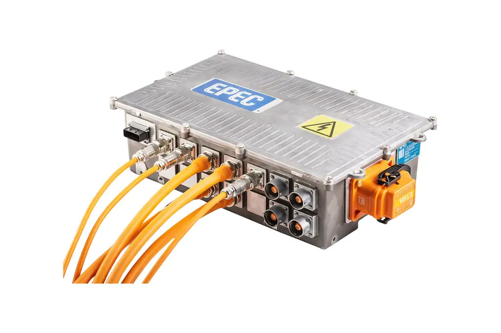
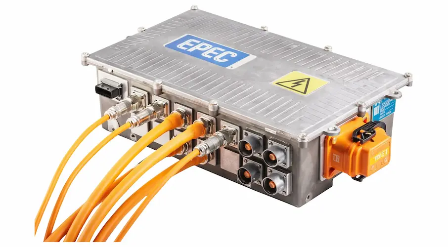
If you opened up an electric heavy-duty vehicle, the PDU would typically look like a robust, rectangular metal box, usually made of die-cast or CNC-machined aluminum.
It is almost always painted silver or black, but it is instantly recognizable by the thick, bright orange high-voltage cables protruding from its heavy-duty connectors.
Inside, it looks like a highly organized, dense electrical panel. You will see thick copper busbars zig-zagging between large cylindrical relays and ceramic fuses. The layout is meticulously designed to keep high-voltage power paths as short as possible while maximizing the physical distance (creepage and clearance) between the high-voltage and low-voltage communication wires.
What Are The Benefits Of The PDU In A Battery Pack System?
Why centralize all this hardware? Why not just bolt relays and fuses directly to the battery modules?
1. Centralized Safety & Homologation
By putting all high-voltage switching in one IP67-rated box, it is much easier to test, validate, and certify. For OEMs aiming for global homologation like UN38.3 or ECE R100.3, a centralized PDU simplifies the compliance process immensely.
2. Ease of Servicing
If a contactor fails or a fuse blows, technicians do not have to tear apart the entire battery pack and expose themselves to live cell modules. They can simply open the PDU enclosure or swap the entire unit out. This drastically reduces downtime for commercial fleets.
3. Modular Integration
At Astraion Dynamics, our transparent “Bring Your Own Cells/Modules” model allows customers to secure raw modules directly from top cell manufacturers at zero middleman markup. Because the PDU is a separate, engineered subsystem, we can design a custom PDU that adapts those standard raw cells to the specific high-voltage requirements of any unique vehicle platform.
What Are The Disadvantages Of The PDU In A Battery Pack System?
While indispensable, PDUs do present engineering challenges.
Packaging Constraints: Space is always at a premium in vehicle design. A PDU adds volume. Finding the physical real estate for a bulky PDU in a compact off-highway machine can be a headache for Vehicle Integration Engineers.
Thermal Bottlenecks: Pushing 500+ amps through contactors and copper busbars generates a lot of heat. If the PDU is not properly cooled, it can overheat, causing relays to weld or fuses to degrade prematurely.
Added Weight: The rugged aluminum enclosures, heavy copper busbars, and industrial contactors add significant weight, which can slightly impact vehicle efficiency.
Integration Complexity: Designing the low-voltage CAN communication so the PDU talks seamlessly with the vehicle’s VCU requires deep engineering expertise. Battery projects often fail at the integration stage because these systems are not developed as one coordinated solution.
How To Design A PDU In A Battery Pack System?
Designing a PDU is not a plug-and-play exercise. It requires application-driven engineering built around real platform constraints.
Here is how top-tier engineering teams approach PDU design:
Phase 1: Application Profiling
Before opening CAD software, you must define the electrical targets. Are you designing for a heavy electric truck that requires massive, sustained current for towing? Or a marine vessel that requires extreme waterproofing and liquid cooling? The continuous current, peak current, and system voltage (e.g., 400V vs 800V) dictate the size of every internal component.
Phase 2: Component Sizing & Selection
Engineers must select contactors and fuses that can handle the worst-case scenario. If your battery pack can output a short-circuit current of 10,000 amps, your main fuse must be able to interrupt that cleanly without shattering, and your contactors must not weld shut before the fuse blows.
Phase 3: Mechanical and Thermal Engineering
Next comes the 3D design and thermal simulation. Engineers route the copper busbars to ensure they don’t cross low-voltage signal wires to prevent EMI. They design the CNC-machined enclosure to withstand heavy vibrations. For extreme applications, they may even integrate a liquid cold plate into the bottom of the PDU to pull heat away from the busbars.
Phase 4: Control Logic Architecture
The hardware is useless without software. The VCU/Controls Engineer must program the exact timing of the pre-charge sequence, the diagnostic checks, and the fault-response times.
Thinking about building your own battery system? Don’t risk project failure at the integration stage. At Astraion Dynamics, we offer turnkey integration across mechanical, thermal, electrical, and controls. Let us master engineering while you control the chemistry.

How To Produce A PDU In A Battery Pack System?
Transitioning from a 3D CAD model to a reliable, mass-produced unit requires a robust manufacturing ecosystem.
1. Precision Fabrication:
The housing is typically die-cast or CNC machined. The copper busbars are laser-cut, bent, and often nickel-plated to prevent oxidation and reduce contact resistance.
2. Assembly:
Because this is high-voltage equipment, assembly is executed by strategic networks of IATF-16949 certified partners under strict quality control. Technicians assemble the components using calibrated torque tools—a loose bolt on a high-voltage busbar can cause a localized hotspot and start a fire.
3. 100% End-of-Line (EOL) Testing:
You cannot leave safety to chance. Every single PDU must go through 100% End-of-Line testing protocols. This includes:
Hi-Pot (High Potential) Testing: Pumping high voltage into the unit to ensure the insulation doesn’t break down.
Continuity & HVIL Testing: Ensuring all internal wiring and interlock loops function correctly.
Leak Testing: Pressurizing the sealed enclosure with air to verify the IP67+ waterproof rating.
Only after passing these tests is the PDU cleared for integration into the final battery system.
Why Is The PDU Important In A Battery Pack System of EVs?
For passenger EVs, commercial trucks, and energy storage systems, the PDU is the absolute heart of system safety.
Think about it: raw lithium-ion cells hold massive amounts of kinetic energy. Tier-1 cell manufacturers are built for standard volume, but they leave the deep customization and safety integration up to you.
Without a meticulously engineered PDU, a simple fault—like a damaged cable—could result in uncontrolled current flow, leading to thermal runaway. In applications like battery electric mining vehicles, which demand highly reliable and explosion-proof systems, a faulty PDU is not just an inconvenience; it is a critical safety hazard.
Furthermore, the PDU dictates the reliability of the vehicle. If your contactors degrade because of a poorly designed pre-charge circuit, your commercial fleet gets stranded. The PDU ensures that the immense power of your battery pack is delivered smoothly, efficiently, and with uncompromising safety every single time the key is turned.
Conclusion
To wrap things up: a PDU (Power Distribution Unit) is the vital high-voltage control center of any EV battery pack.
It takes the raw, volatile power generated by the battery cells and safely manages its distribution to the vehicle. By housing crucial components like high-voltage relays, pre-charge circuits, intelligent BMS modules, and robust fuses within a rugged IP67 enclosure, the PDU ensures flawless operation and total system safety.
For engineering managers, and integration teams, getting the PDU right is often the hardest part of the electrification journey. It bridges the gap between raw cell chemistry and your customized vehicle platform.
Whether you are building electric agricultural machinery, marine vessels, or heavy-duty trucks, partnering with an engineering-first integrator can drastically shorten your development cycles and bring your platforms into operation with total confidence.
Ready to bypass the engineering headaches and get your platform to market faster?
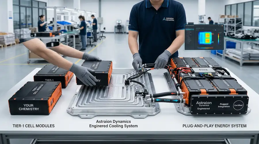
Astraion Dynamics is the ultimate integration hub for heavy-duty, marine, and off-highway applications . You negotiate directly with cell manufacturers for the best pricing, and we turn those modules into fully certified, plug-and-play energy systems.
[Click Here to Schedule a Technical Consultation with Our Chief Engineers Today]
